
Diode pumped laser with intracavity harmonics

a diode pumped laser and harmonic technology, applied in semiconductor lasers, laser details, optical resonator shape and construction, etc., can solve the problems of limited efficiency of external harmonic conversion, and limited lifetime considerations of conversion process efficiency, so as to achieve the effect of optimizing the overall conversion

Inactive Publication Date: 2006-03-21
NEWPORT CORP
View PDF19 Cites 36 Cited by
  • Summary
  • Abstract
  • Description
  • Claims
  • Application Information

AI Technical Summary

Benefits of technology

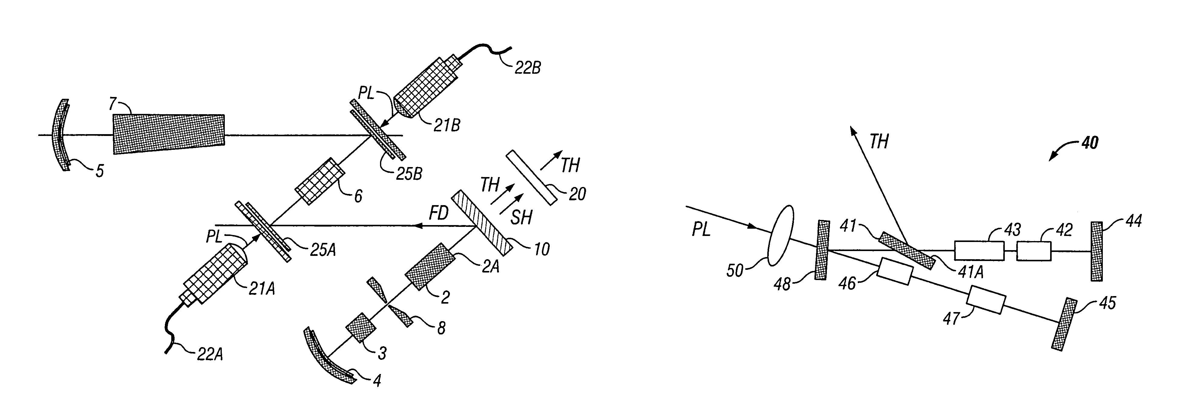
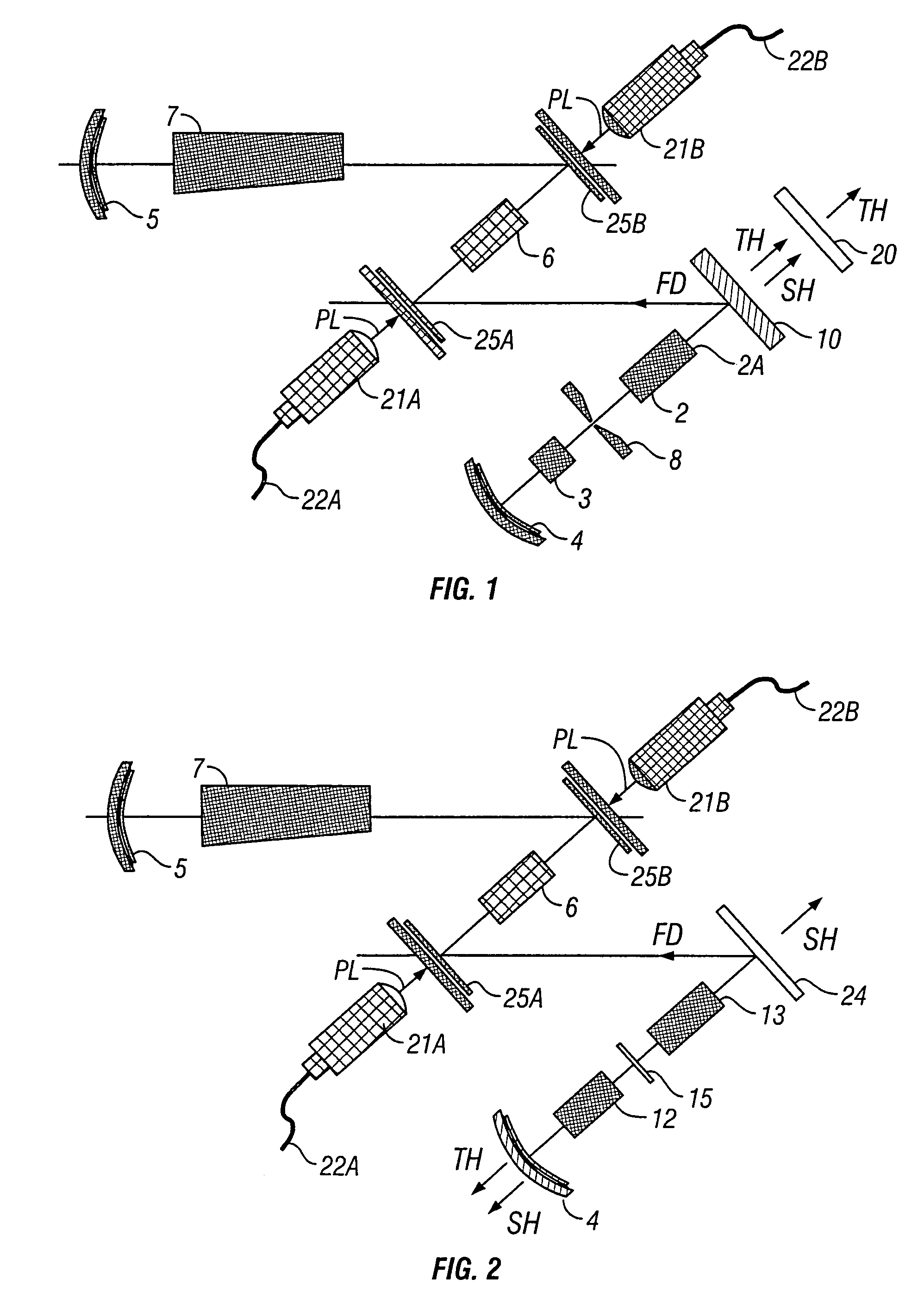
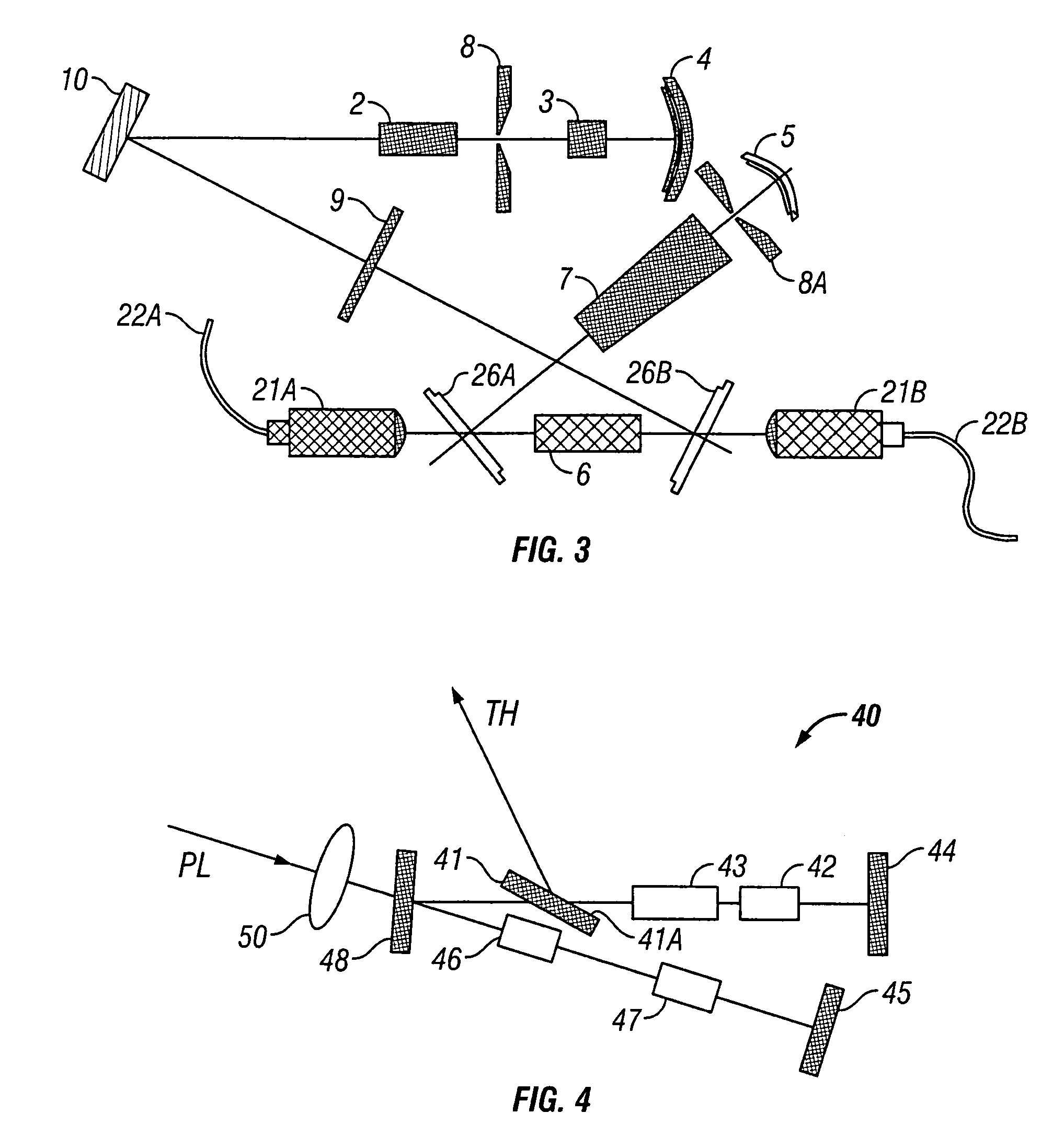
The present invention provides design platforms for lasers that can be flexible enough to be adaptable to different application environments, including low and high power regimes. The use of intracavity techniques with high reflector mirrors and circular output beams can provide higher efficiency and longer lifetime for harmonic wavelengths compared to extra-cavity techniques. The invention also includes the use of simple cavities with relatively few optical components and slowly varying fundamental spot sizes in the harmonic generator crystals. The lasers can operate at high repetition rates and have high overall conversion efficiency. The invention also provides improvements in the performance of harmonic wavelengths at low power densities.

Problems solved by technology

Generally, the art recognizes that the efficiency of the external harmonic conversion is limited by the available peak power of the fundamental laser and damage to the coatings of the nonlinear crystal.
On the other hand, coatings applied to the crystal as well as to other optical elements in the harmonics path are known to be increasingly susceptible to damage as the power density or the fluence increases, hence the efficiency of the conversion process is limited by lifetime considerations.
These limitations tend to become progressively more severe at higher harmonics because of the propensity for damage to coatings and even bulk materials to occur more readily at shorter wavelengths especially as the higher harmonics get deeper into the UV.
In diode pumped systems, both of those options are subject to inherent limitations, especially for higher repetition rates.
For such systems, requiring also higher energy outputs lead to average powers that are not consistent with stable TEM00 operation of the cavity due to thermal lens and stress aberration considerations.
Thus, both average and peak power scalability in diode end-pumped systems are limited, even as more diode pump power becomes available.
Using two rods and additional pump ports has demonstrated pulsed power scaling of up to 50 W (see Hodgson et al, CLEO 2001 Proceedings, Paper CThC4) but this comes generally at the expense of longer, more complex cavities and longer pulse durations, as well as decreased output power stability at higher repetition rates.
However, most of the intracavity converted pulsed lasers available to date, have multi-mode beam quality, which provides a poor match to many industrial applications of interest.
Both of these early patents failed, however, to appreciate the difficulties inherent to using dichroically coated elements to extract and / or isolate the higher harmonics when the infrared fundamental laser beam is optically coupled and collinear with the generated harmonic radiation.
Also disclosed in this patent are intracavity UV reflecting mirrors which are useful in blocking the UV radiation from reflecting back towards the main cavity and other crystals b, However, Zhou et al failed to note that such constructions of harmonic sub-cavities require dichroic and trichroically coatings, which are known to be difficult to manufacture in practice and are generally more susceptible to damage than standard coatings, especially when subjected to high intensity UV beams.
In practice, the use of dispersive surfaces such as intra-cavity prisms or Brewster plates tend to lead to long asymmetric resonators with each additional such element adding to the design complexity.
In high power laser operation, this may adversely affect the stability conditions for TEM00 operation and complicates the laser alignment.
Longer resonators may also result in longer pulse durations than is desired for the applications contemplated.
Although such an elliptical beam can be made more circular through use of tilted, curved reflectors, cylindrical optics or a fused silica Littrow prism, including such optics in the cavity will complicate the overall resonator design, potentially negating the purpose of the original compact, readily aligned construction.
The system with a Brewster cut tripler also does not readily extend to higher harmonics, being suited only to the specific harmonic for which it is designed.
Although recognizing the importance of stable TEM00 operation in intracavity converted lasers, the known art has also failed to address the ramifications of requiring operation in the stable regime in the presence of intracavity elements across a range of output parameters.
Generally, it is well known in the art of solid state lasers that, as the pump power incident on a laser crystal is increased, thermal lensing becomes a limiting factor for diffraction limited operation.
Although such a strong lens can be compensated by clever cavity design, the aberrations in the lens eventually degrade the single mode performance of the laser.
This in turn sets limits on the spot sizes that may be utilized in the nonlinear crystals, thus affecting the overall harmonic conversion efficiency.
Setting the laser parameters in this manner is, however, neither necessary nor sufficient in terms of providing stable TEM00 operation over a desirable range of repetition rates at either low or high power.
In particular, it has already been recognized that beam separation is a particularly challenging aspect of any intracavity harmonic conversion process, especially for high power systems.
Therefore, extracting one particular desirable wavelength while suppressing others will, as a rule, require more complex separation schemes as compared with those commonly utilized in externally converting systems.
The difficulties are compounded at the high peak powers characteristic of pulsed resonators, and an intracavity pulsed system is known to be very demanding of the resonator optics, especially if any light in the UV portion of the spectrum is produced, as optics are generally become less damage resistant as the wavelength becomes shorter.
Thus, circulating UV light, even in relatively small amounts can damage AR coatings including those protecting sensitive laser rod and nonlinear crystals.
Typically, optics used in known systems for beam separation involved dichroic and trichroic coatings or dispersive surfaces, each with its attendant disadvantages and challenges.
Thus, dichroic or trichroic coatings with the requisite reflection and transmission properties can be difficult to design and they remain generally susceptible to damage.
For example, coating a standard flat optic for high transmission in the green and UV and high reflection in the infrared is known to be a difficult problem.
With all three wavelengths incident on the same spot, an imperfect coating can undesirably absorb some of the UV light, becoming “thermalized”.
This can result not only in unpredictable power output drops but in general instability of the laser.

Method used


Image

  • Diode pumped laser with intracavity harmonics
  • Diode pumped laser with intracavity harmonics
  • Diode pumped laser with intracavity harmonics

Examples


embodiment 90

[0085]Referring now to FIGS. 10A and 10B, the techniques shown represent optical realizations of the functional element previously represented by numeral 10 and 11 in FIGS. 1 and 2, respectively. FIG. 10A shows an embodiment 90 for beam separation comprising two tilted dichroic plates 91 and 92. Tilted plate 91 is generally coated on side 91 A for high reflection in the UV and high transmission at other wavelengths. Use of an angled plate makes the design of such dichroic coating generally easier than for a flat plate. Furthermore, the angle can be selected to also provide additional dispersion between the visible and UV beams so that a portion of the second harmonic (designated SH) is reflected from plate 91, generally off-set by some angle from the UV beam. A second tilted plate 92 is coated on side 92A for high reflection of the green and high transmission in the infrared. Again, the tilt on plate 92 deflects any remaining UV light away from the path of the fundamental beam, desi...

embodiment 95

[0086]An alternative embodiment 95 using dual dichroic coating is shown in FIG. 10 B, where a single tilted plate 96 is used with the feature that it has two different dichroic coatings on its two sides. Side 96 A is coated for high reflection at the UV wavelength and high transmission for the visible and infrared. Side 96 B is coated for high transmission in the infrared and high reflection in the visible. The plate's thickness and angle are chosen to provide sufficient separation between the UV and visible beams allowing extraction of the UV beam, again with high purity.

[0087]Note that both of the above embodiments use combination of tilted surface and dichroic coatings assures higher purity of the spectral content the desired harmonic than is possible with coatings alone, which are known to be imperfect.

[0088]Still another embodiment is shown in FIG. 11 which is designed to overcome the disadvantages of trichroically coated optics. As was mentioned above, the proximity of the 355...


PUM


Abstract

A diode end-pumped solid state laser is provided which produces improved power output, long term stability and improved conversion efficiency from the pumping power, high as well as low power operation while maintaining certain desirable common characteristics such as TEM00 operation, circular outputs, readily aligned systems and compatibility with long lifetime for all components. The invention intracavity conversion to second, third and higher harmonics in several different spectral regimes. The invention also addresses the aspects of design flexibility, seeking in certain embodiments to provide a single platform for providing several harmonic beams.

Description

BACKGROUND[0001]1. Field of the Invention[0002]The present invention relates to the field of frequency converted solid state laser, and in particular to intracavity frequency conversion.[0003]2. Description of the Related Art[0004]Laser radiation at visible and UV wavelengths with high average power and repetition rates is useful for numerous industrial applications ranging from via hole drilling, laser texturing, micromachining, stereophotolithography, memory repair and direct writing. Medical applications including surgical and other therapeutic procedures can also benefit from availability of high power at shorter wavelengths, especially from compact and reliable devices.[0005]In conventional solid state laser systems based on second, third or fourth harmonic generation, the output is typically produced in an extracavity module, using one or more nonlinear crystals. Generally, the art recognizes that the efficiency of the external harmonic conversion is limited by the available p...

Claims


Application Information

Patent Timeline
Patent Type & Authority Patents(United States)
IPC IPC(8): H01S3/091H01S3/094H01SH01S3/08H01S3/081H01S3/083H01S3/0941H01S3/10H01S3/109H01S5/00
CPCH01S3/109H01S3/09415H01S3/08045H01S3/0805H01S3/0817H01S3/0813
Inventor DUDLEY, DAVID R.HODGSON, NORMANHOFFMAN, HANNA J.MEHL, OLIVER
Owner NEWPORT CORP
Learn More