[0024]Accordingly, it is an object of the present invention to provide a method for minimizing the life cycle cost of processes, particularly industrial processes. While a preferred embodiment of the present invention herein describes the method as it might be applied to the heating of a building, those having ordinary skill in the art will recognize that the method of the present invention is not limited to a
heating system, and may be successfully deployed across a wide variety of industrial processes. While not meant to be limiting, processes for which the present invention would provide an economic benefit include high safety consequence processes, such as nuclear processes, e.g. nuclear electrical power generating plants, nuclear waste
vitrification and packaging plants,
nuclear fuel manufacturing and reprocessing facilities, chemical processes, special chemical manufacturing involving carcinogens or pesticides), general chemical manufacture (e.g.,
fertilizer, plastics, pharmaceuticals), and
petroleum refining;
high energy consumption processes, such as aluminum
smelting and steel production; high material and / or machinery consumption processes, such as automobile manufacturing,
food preparation, and heating and cooling; and
high skill level requirements processes such as microchip manufacturing,
machining processes,
fossil fuel electrical generation, and combined heat and power installations. Accordingly, the method of the present invention is broadly applicable to any process that utilizes a variety of disparate pieces of equipment which are operated independently of one and another or in concert. Thus, while the present invention is described in highly specific detail using the heating of a building as an example, the invention should be broadly construed to encompass any process utilizing pumps, boilers, fans, heat exchangers, chillers, fans,
solid oxide fuel
cell stacks, rooftop
package units,
HVAC systems, pumps, motors, and defouling monitors and equipment, or other pieces of similar or complementary equipment.
[0025]The present invention thus performs a series of automated steps, the objects of which are designed to provide meaningful information to optimize the operation and maintenance of a process in a manner which allows the minimization of its overall life cycle cost. Toward that end, the first object of the present invention is to identify a set of optimal operating conditions for the process.
[0041]These and other objects of the present invention are satisfied by providing the comprehensive system of the present invention that both monitors and optimizes a process by utilizing a
library of algorithms constructed according to best
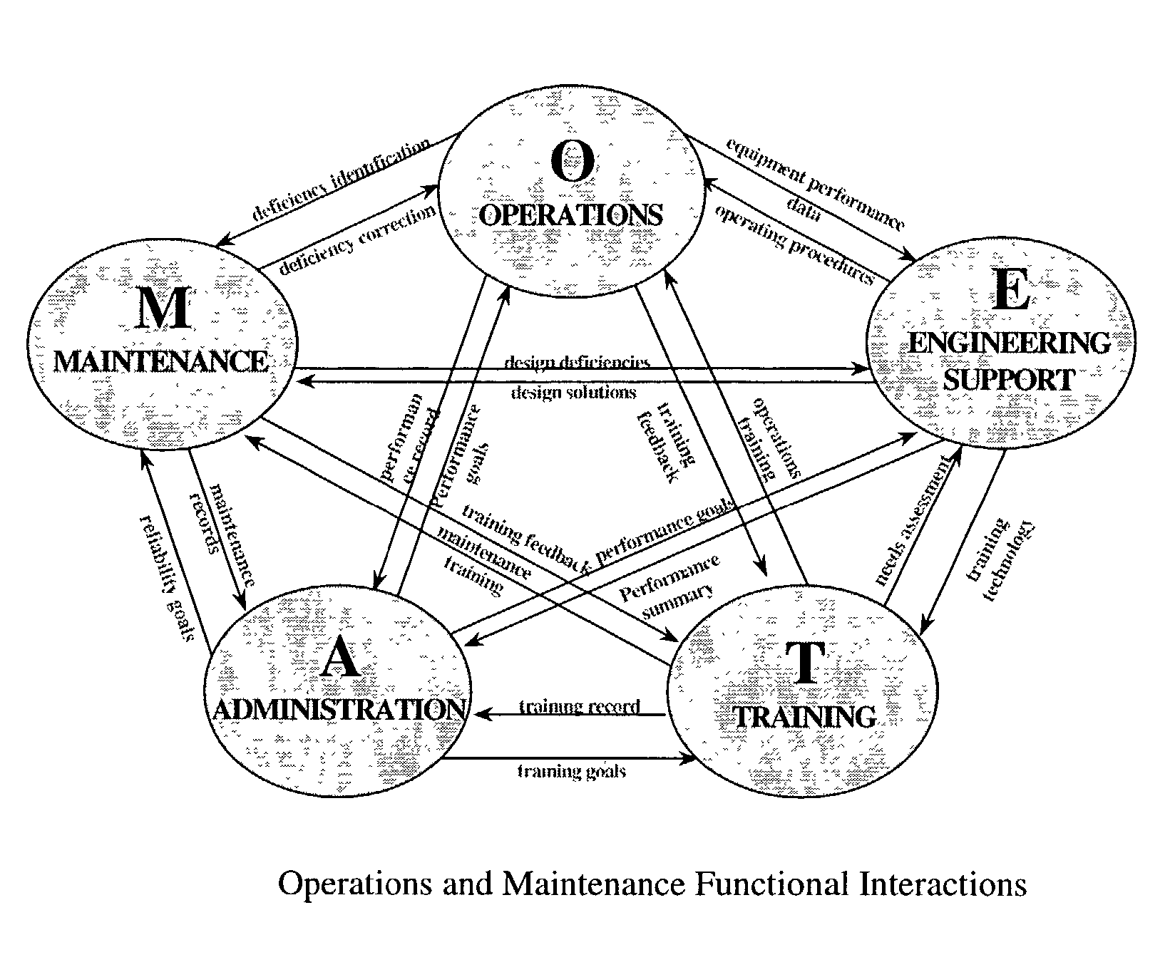
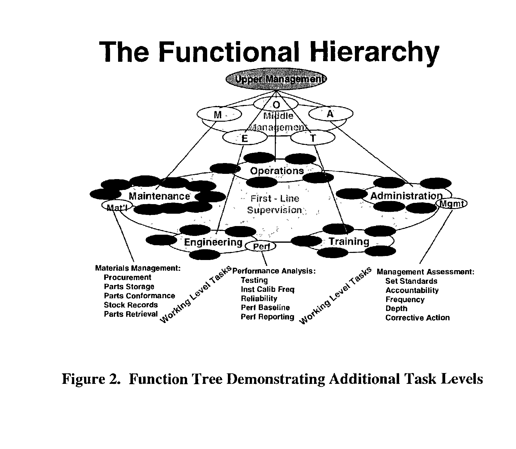
engineering practices, the out put of those algorithms being tied to specific functions, such as
engineering, maintenance, operations, etc. to allow optimal operation, maintenance and repair of the process. It should be noted that in many cases, while the
library of algorithms are applicable to specific pieces of equipment, they are not constructed in a manner that renders them vender specific. Rather, the algorithms are generalized to allow the system to be rapidly and inexpensively implemented in a variety of installations that
use equipment having the same or similar functions produced by a variety of manufacturers and configured in a variety of ways at a specific location. While this flexibility of the present invention can be readily appreciated with an understanding of a detailed description of a preferred embodiment, it will be apparent to those skilled in the art that many changes and modifications may be made without departing from the invention in its broader aspects. The appended claims are therefore intended to cover all such changes and modifications as fall within the true spirit and scope of the invention.

