Long life intelligent illuminated road marker

a technology of intelligent illumination and road markers, which is applied in the direction of road signs, roads, constructions, etc., can solve the problems of reducing the amount of light that is effectively reflected from the marker back to the vehicle driver, the marker is expensive to install and maintain, and the reflection of the marker is not good, so as to reduce the deterioration of the battery and the housing. , the effect of long operating li

Inactive Publication Date: 2006-03-28
JORDAN WESLEY B
View PDF17 Cites 41 Cited by
  • Summary
  • Abstract
  • Description
  • Claims
  • Application Information

AI Technical Summary

Benefits of technology

[0015]The present invention provides advantageous solar powered road markers constructed such that the markers have a long life without requiring any maintenance. In addition, certain embodiments are designed such that the marker can be “on” continuously, rather than having to be shut down during high illumination periods. The markers are generally designed using a single piece housing, constructed of a material that is resistant to abrasion, as well as to discoloration and other degradation due to UV light exposure, and utilizes a battery system that tolerates trickle charging while still providing a long operating life. As a result, by limiting deterioration of the housing and the battery, typically the present markers have an operating life of at least 5 years.
[0031]Indication that a road marker operates “continuously” means that the marker is illuminated without an interruption based on external environmental condition, or an interruption of longer than 5 seconds, except that a marker operating “continuously” can cease illuminating when the marker is unable to deliver sufficient electrical energy to the light emitting component(s) due to stored energy droping below the minimum for such illumination.
[0040]The term “fog sensor” refers to a detection device that detects scattered light from water droplets suspended in air. In connection with the present road markers, a “fog sensor” detects scattered light from the air above the marker. The marker can then trigger a desired action when the scattered light level reaches a particular level, for example, turn on flashing or increase flash duration.
[0049]The term “bonding material” is used to refer to a material that increases the bond strength for one of the present markers adhered to a mounting surface, such as a road surface. In most cases, the bonding material increases the surface area of the surface on which the bonding material is present, and can also provide shapes and / or compositions that increases bond strength.
[0050]In a related aspect, the invention provides an illuminated road marker that includes a one piece housing formed of a polycarbonate plastic, preferably a non-yellowing polycarbonate. The housing includes a top plate and perimeter sides, where at least one perimeter side includes a light transmission surface through which light can be transmitted, and where the top plate and the sides define a cavity in the housing; a plurality of light emitting diodes (LEDs) positioned within the cavity such that light produced by the LEDs is transmitted through the light transmitting surface, and where the LEDs point in at least two different directions different by 2 to 15 degrees; a long life battery within the cavity that energizes the LED, where the battery tolerates trickle charging without deterioration; a solar cell within the cavity adjacent to the top plate, where the solar cell recharges the battery; electrical circuitry within the cavity configured to control charging of the battery; and encapsulating material filling the cavity. The road marker operates continuously and has an operating lifetime without maintenance of at least 3 years, typically at least 5 years.

Problems solved by technology

However, such reflective road markers do not function well under some adverse conditions, such as inclement weather, e.g., foggy conditions, or where an appreciable coating is present on the surface of the marker, as such conditions substantially reduce the amount of light that is effectively reflected from the marker back to the vehicle driver.
While markers utilizing wires to supply power for the light source can be constructed, such markers are expensive to install and maintain.

Method used


Image

  • Long life intelligent illuminated road marker
  • Long life intelligent illuminated road marker
  • Long life intelligent illuminated road marker

Examples


Embodiment Construction

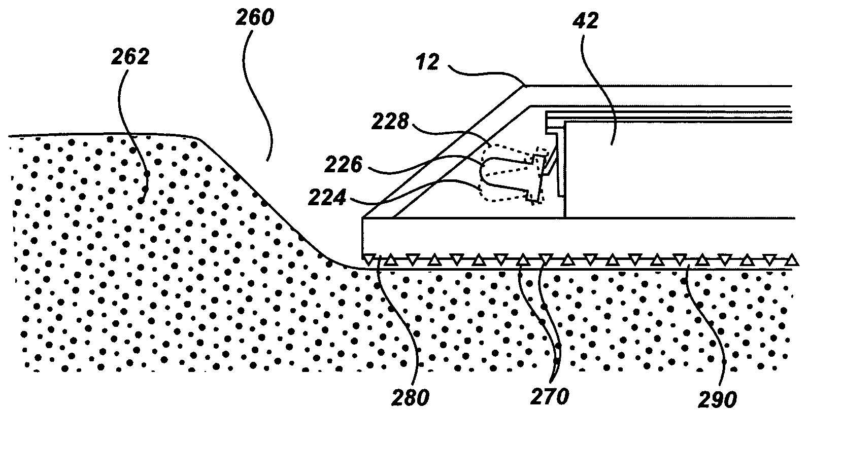
[0067]The present road markers are particularly adapted for highway and remote applications, as they are designed to have long operating life while being mechanically and electronically simple. Nonetheless, the markers can be used or configured for use in many other applications. Such long life is especially advantageous for highway applications as it significantly reduces the costs associated with maintenance and / or replacement. The long operating life is achieved through the use of a suitable housing material, along with suitable combinations of solar cells, batteries, and control circuitry and / or control programming.

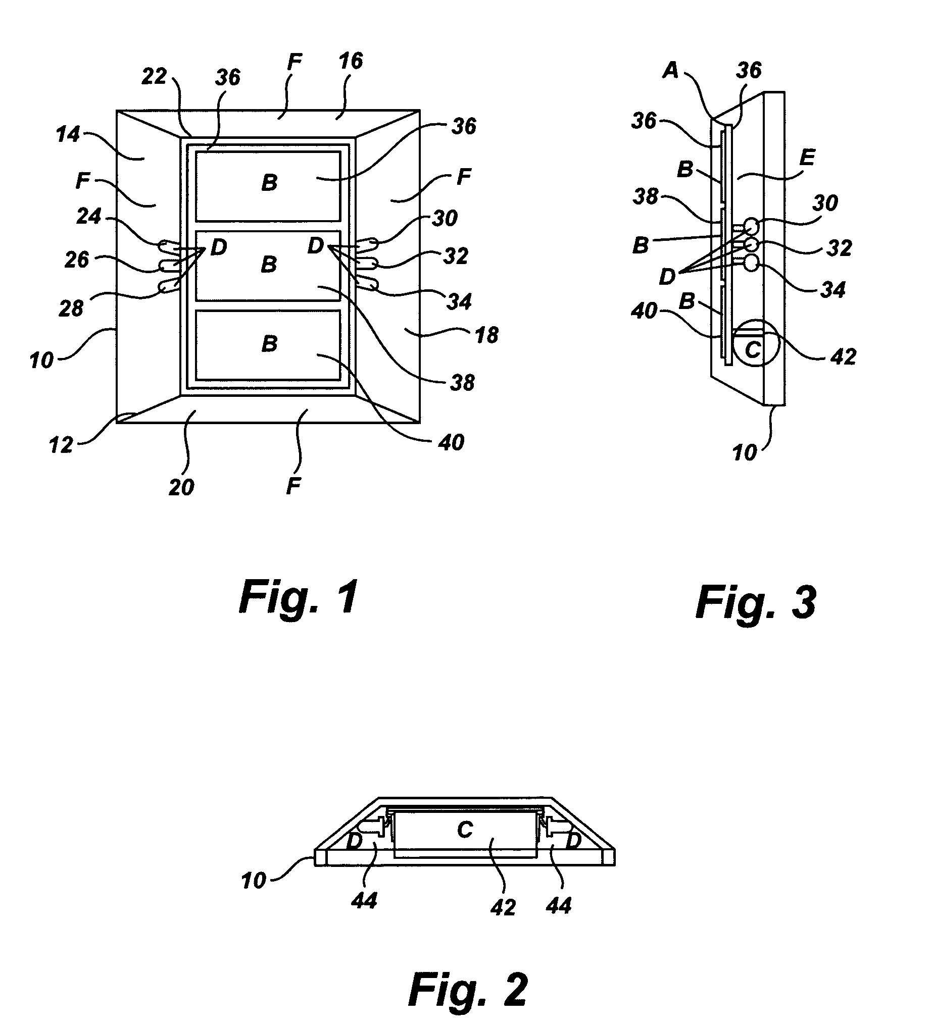
[0068]Typically the road markers include a housing that has a cavity opening downward. The cavity contains the illumination components, including one or more low energy consumption light emitting elements (typically light emitting diodes (LED*s), energy storage components such as batteries (or, if desired, storage capacitors), one or more solar cells, and any needed c...


PUM


Abstract

Self-contained solar-powered long-life intelligent illuminated road markers are provided comprising a one-piece housing formed of optionally colored plastic capable of transmitting light. Light is reflected by reflective coating or generated internally by LED which is powered by a long life battery, the charging of which is controlled by electrical circuitry which comprises a peripheral interface controller. The electrical circuitry provides intelligent control for a variety of modes corresponding to diverse driving conditions, and can enter a low-power sleep mode to conserve battery life.

Description

CROSS-REFERENCE TO RELATED PATENT APPLICATIONS[0001]NOT APPLICABLE.BACKGROUND OF THE INVENTION[0002]The present invention concerns solar powered road markers.[0003]The following information is provided solely to assist the understanding of the reader. None of the information provided or references cited is admitted to be prior art to the present invention.[0004]In most applications, the current road markers are small, rectangular housings that include a reflective material arranged such that light from the headlights from an approaching motor vehicle will be reflected back to the driver, thereby enhancing visibility of the marker. In many cases, the housing is mounted on the road surface or in a small depression in the road surface, typically using an adhesive. However, such reflective road markers do not function well under some adverse conditions, such as inclement weather, e.g., foggy conditions, or where an appreciable coating is present on the surface of the marker, as such con...

Claims


Application Information

Patent Timeline
Patent Type & Authority Patents(United States)
IPC IPC(8): E01F9/06E01F9/00
CPCE01F9/065E01F9/559
Inventor JORDAN, WESLEY B.
Owner JORDAN WESLEY B
Why Eureka
Try Eureka