Method of improving performance of refrigerant systems

a refrigerant system and performance improvement technology, applied in the field of refrigerant system performance improvement, can solve the problems of increasing the energy consumption of refrigerant system, refrigerator and air conditioner collectively consume enormous amounts of energy, etc., and achieve the effect of improving the performance of the refrigerant system such as the refrigerator, freezer, soda fountain dispenser and other cooling devices

Inactive Publication Date: 2006-03-28
COGNIS IP MANAGEMENT GMBH
View PDF239 Cites 39 Cited by
  • Summary
  • Abstract
  • Description
  • Claims
  • Application Information

AI Technical Summary

Benefits of technology

[0007]It has now been found that the performance of a refrigerant system such as in air conditioner, refrigerators, freezers, soda fountain dispensers and other cooling device is improved by using working fluids consisting essentially of a heat transfer fluid and lubricant that are miscible over the operating temperature range of the system. This finding applies to a re

Problems solved by technology

Refrigerant systems such as refrigerators and air conditioners collectively consume enormous amounts of energy.
Energy consumption of refrigerant systems is likely to increa

Method used


Image

  • Method of improving performance of refrigerant systems
  • Method of improving performance of refrigerant systems
  • Method of improving performance of refrigerant systems

Examples


example 1

AND A

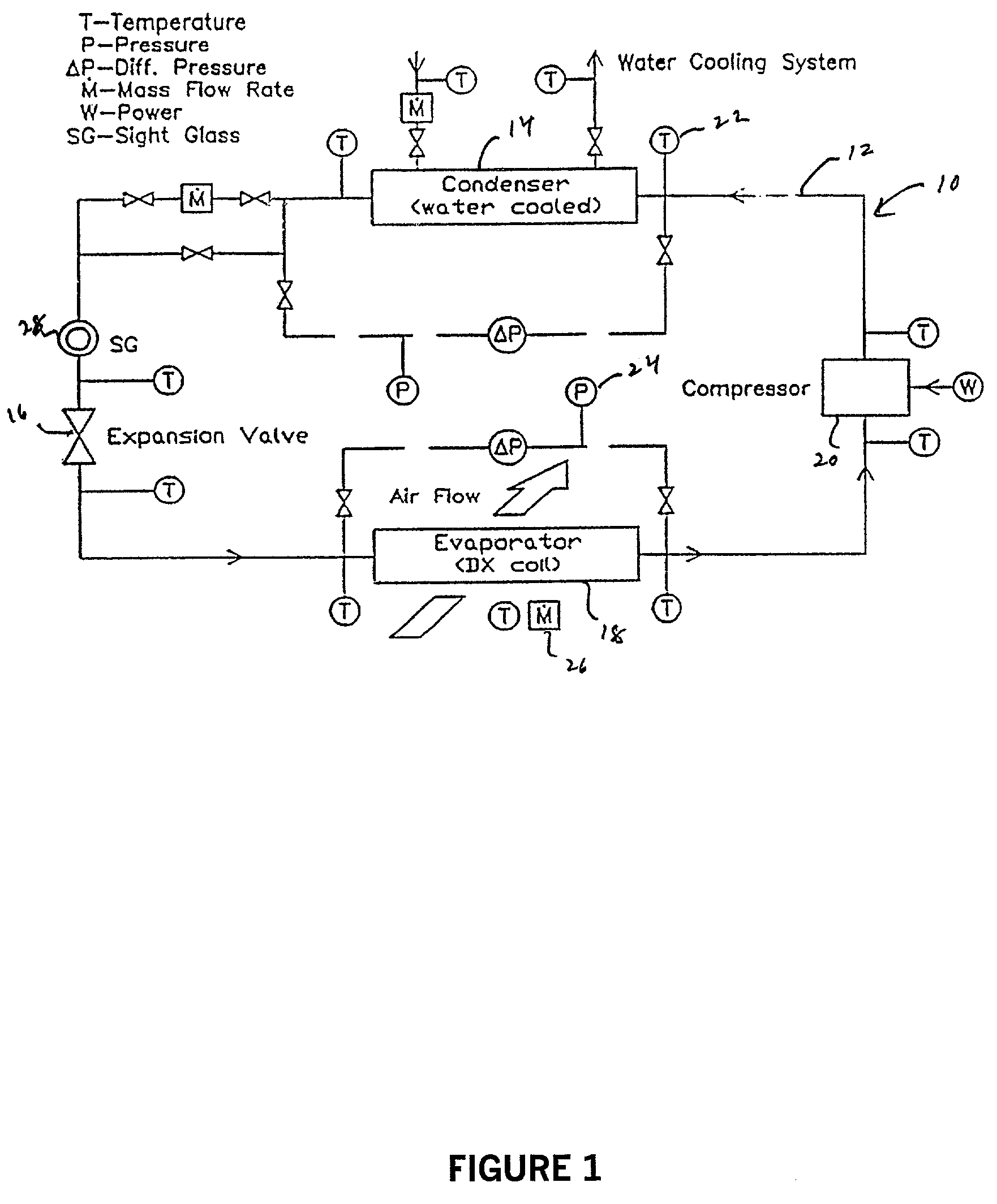
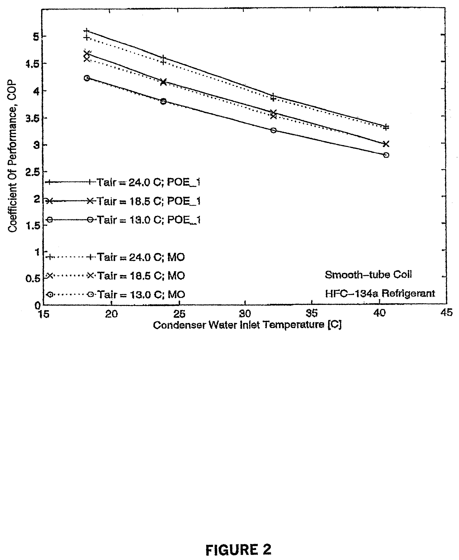
[0063]Two refrigerant working fluids were tested in a vapor compression refrigeration system similar to that described in FIG. 1. One of these fluids (Example A) comprises a heat transfer fluid and a mineral oil lubricant known to be immiscible with the heat transfer fluid. The mineral oil is an Iso 32 naphthentic refrigeration oil. The second working fluid (Example 1) comprises a lubricant comprising a polyol ester which is known to be miscible with the heat transfer fluid. The heat transfer fluid used in both Examples A and 1 is 1,1,1,2-tetrafluoroethane (R134a). The polyol ester of Example 1 is formed from pentaerythritol and a mixture of 37 weight percent n-pentanoic acid, 20 weight percent of a mixture of 2-methylbutanoic acid and 3-methylbutanoic acid and 43 weight percent 3,5,5-trimethylhexanoic acid.

[0064]These refrigerant working fluids were tested in a vapor-compression refrigeration system similar to that used in actual buildings. This system is designed to provide a...

example 2

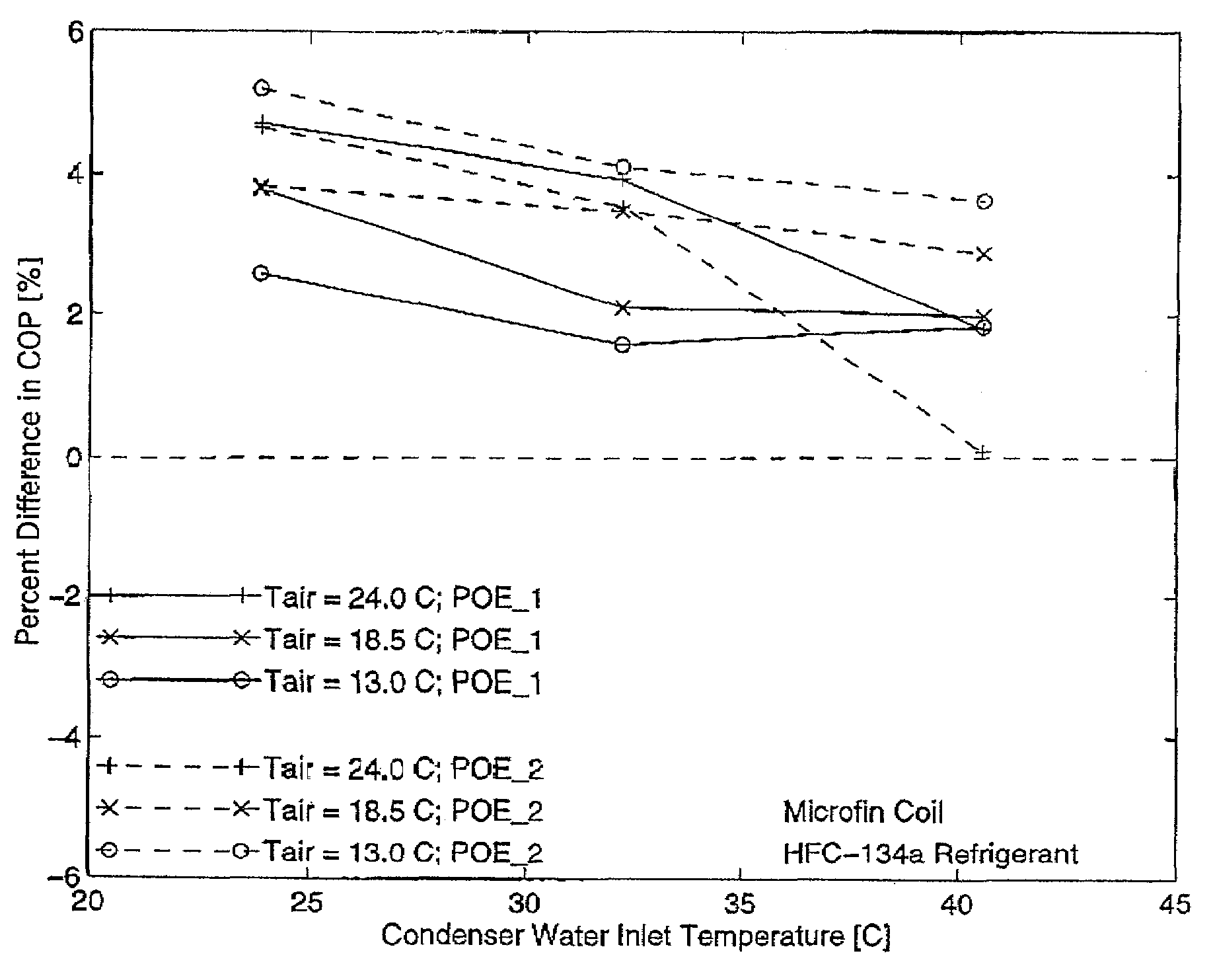
[0103]The coefficient of performance was measured for refrigeration apparatus described hereabove using a second miscible working fluid comprising 1,1,1,2-tetrafluoroethane heat transfer fluid and a second polyol ester lubricant (POE #2). The second polyol ester is formed from an alcohol mixture of 65 weight percent pentaerythritol and 35 weight percent dipentaerythritol and a mixture of straight chain acids of 5 to 10 carbon atoms present in the following ranges (53–63 no. % nC5; 5–15 no. % nC6; 7–17 no. % nC7; 7–17 no.% nC8; 0–10 no. % nC9 and 0–10 no. % nC10 The conditions under which the coefficient of performance was measured for this Example 2 working fluid were the same as those for the working fluids of Examples 1 and A. The comparative results for COP for the miscible working fluids of Examples 1 and 2 (expressed as POE #1 and #2) are shown in FIG. 6.

[0104]The coefficient of performance results of the working fluids of Examples 1 and 2 are defined relative to the immiscible...


PUM


Abstract

A method of improving performance of refrigerant systems such as refrigerators and air conditioners that utilize a refrigerant working fluid. The working fluid consists essentially of a heat transfer fluid and a lubricant that is miscible and is otherwise compatible with the heat transfer fluid at all operating temperatures of the refrigerant system. The method is directed particularly to chlorine-free fluoro-group organic fluids and more particularly to hydrofluorocarbon heat transfer fluids. The preferred lubricants comprise polyol ester basestocks and compounded polyol esters that are highly miscible with such hydrofluorocarbon heat transfer fluids.

Description

CROSS-REFERENCE TO RELATED APPLICATIONS[0001]This application is a continuation application of U.S. patent application Ser. No. 09 / 328,858 filed Jun. 9, 1999 now abandoned.FIELD OF THE INVENTION[0002]This invention relates to a method or process of improving performance of refrigerant systems such as refrigerators and air conditioners that utilizes a working fluid. The working fluid consists essentially of a chlorine-free fluoro-group containing heat transfer fluid and a lubricant that is miscible phase and is otherwise compatible with the heat transfer fluid over the operating temperature of the system. The heat transfer fluid is preferably a hydrofluorocarbon. The lubricant preferably comprises an ester formed from an alcohol containing at least two —OH groups and a carboxylic acid that is substantially or exclusively monovalent.BACKGROUND OF THE INVENTION[0003]Refrigerant systems such as refrigerators and air conditioners collectively consume enormous amounts of energy. Energy co...

Claims


Application Information

Patent Timeline
IPC IPC(8): C09K5/04C09K5/06C10M105/38F25B1/00C10M171/00C10N40/30
CPCC09K5/045C10M105/38C10M171/008C10N2240/66C10M2207/281C10M2207/282C10M2207/283C10M2207/286C10M2209/109C10M2211/022C10M2211/06C10N2240/00C10N2240/22C10N2240/30C10N2240/50C10N2240/52C10N2240/54C10N2240/56C10N2240/58C10N2240/60C09K2205/24C10N2040/00C10N2040/34C10N2040/30C10N2040/40C10N2040/38C10N2040/32C10N2040/42C10N2040/36C10N2040/44C10N2040/50
Inventor SCHNUR, NICHOLAS E.BEIMESCH, BRUCE J.
Owner COGNIS IP MANAGEMENT GMBH
Why Eureka
Try Eureka