Device for the inductive transmission of electrical power

Inactive Publication Date: 2006-03-28
CONDUCTIX WAMPFLER
View PDF13 Cites 30 Cited by
  • Summary
  • Abstract
  • Description
  • Claims
  • Application Information

AI Technical Summary

Benefits of technology

[0008]It is particularly advantageous to utilize a cable that has been specifically optimized for a combination of a data line with a power line in accordance with this invention, wherein the expenditure required for the joint laying of both lines as well as the risk of a faulty laying is

Problems solved by technology

This concept, however, results in the problem that the data line must be inductively coupled sufficiently closely to the mobile pick-up with

Method used


Image

  • Device for the inductive transmission of electrical power
  • Device for the inductive transmission of electrical power
  • Device for the inductive transmission of electrical power

Examples


Embodiment Construction

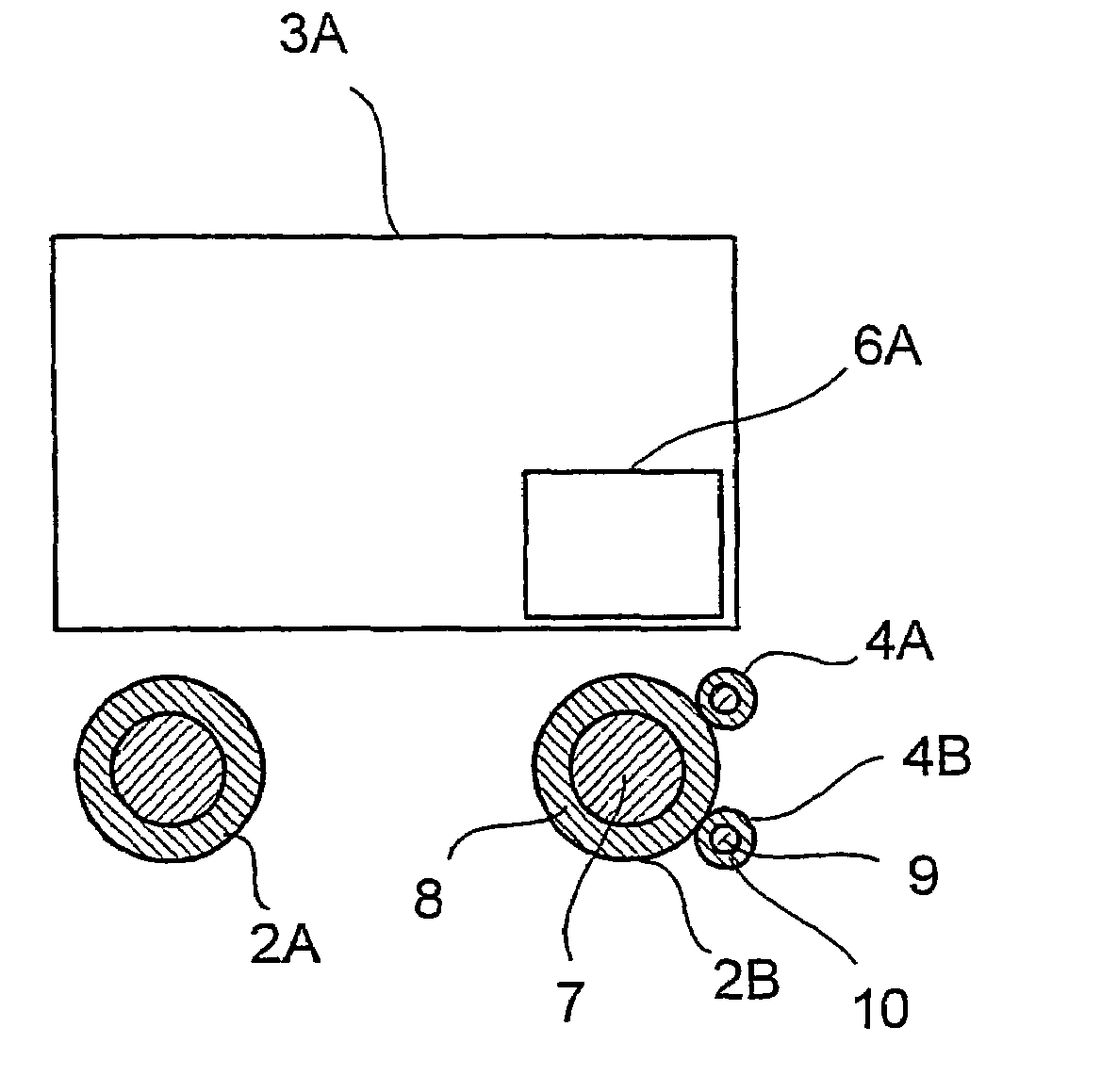
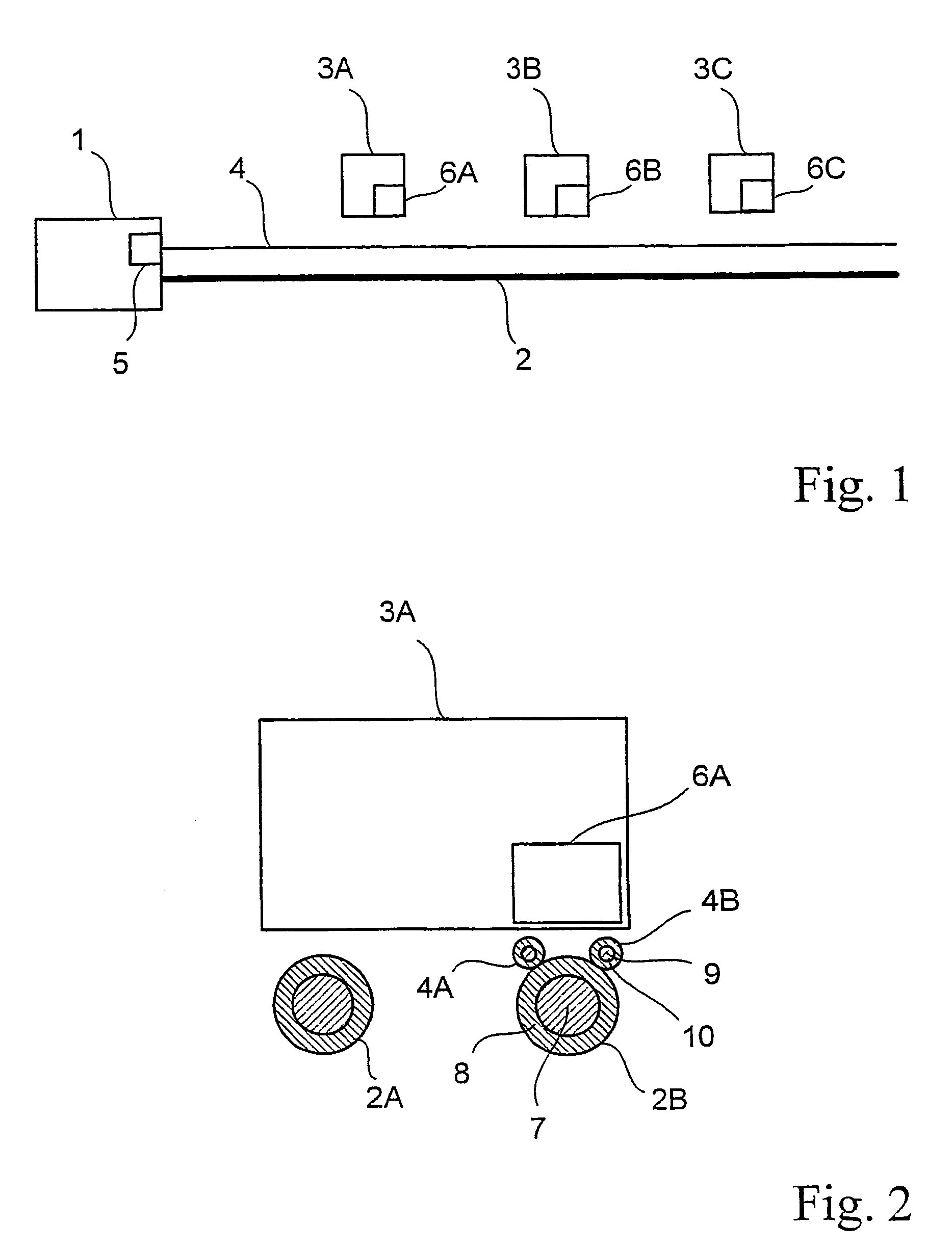
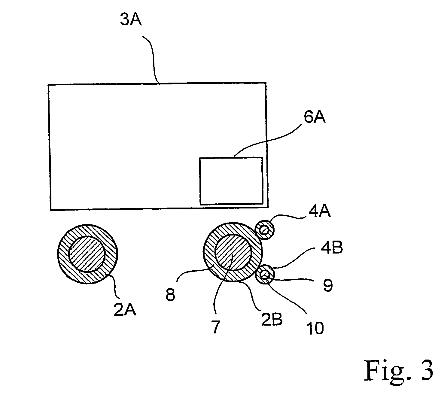
[0014]As shown schematically in FIG. 1, a system for inductive transmission of electrical power comprises power supply electronics 1, and a power line 2, as well as one or a plurality of mobile pick-ups 3A through 3C, while 3 pick-ups represented by pick-ups 3A through 3C are employed in FIG. 1 for purely illustrative purposes. The power supply electronics 1 furnish alternating current to the power line 2, which is formed as a loop, while each respective pick-ups 3A through 3C is inductively coupled thereto. Each pick-up 3A through 3C represents at the same time a constituent part of a mobile user along the power line 2 because the pick-up is provided with alternating voltage thanks to said inductive coupling. This voltage can be converted depending on the need of pick-up. It is thus possible for example to produce direct voltage in this location by means of a rectifier and a switch controller of a known art.

[0015]In accordance with the invention, a data line 4 runs parallel to the ...


PUM


Abstract

The invention relates to a device for the inductive transmission of electrical power, comprising a power line which is situated on the primary side of said device and which consists of two wires which are guided in a parallel manner relative to each other. Power can be drawn from line by at least one mobile consumer, which is situated on the secondary side, by means of inductive coupling. Said device is provided with a data line which is situated on the primary side for the additional inductive transmission of data to and/or from the consumer. Said data line consists of two wires which are guided in a parallel manner relative to each other. Each of the data line wires is arranged adjacent to one of the two power line wires and in a manner that is symmetrical to a plane. The cross section of the conductor of the adjacent wire of the energy line is also symmetrical relative to the plane. The inductive coupling between the power line and the data line can be thus kept very low, and simultaneously enables the inductor, which is to be provided on the secondary side for the magnetic coupling with the data line, to be integrated into or mounted on the energy-transmitting consumer. The data line can be fixed to the power line or both lines can be integrated therewith in a common cable.

Description

CROSS REFERENCE TO RELATED APPLICATIONS[0001]This application is a U.S. National Stage entry of co-pending International Patent Application No. PCT / EP02 / 06765, filed on Jun. 19, 2003 by BÖHLER, Frank et al. entitled DEVICE FOR THE INDUCTIVE TRANSMISSION OF ELECTRICAL POWER, the entire contents of which is imcorporated by reference, and for which priority is claimed under 35 U.S.C. § 371. As in the parent International Application No. PCT / EP02 / 06765, priority is also claimed to co-pending Germany Patent Application No. 101 31 905.3, filed on Jul. 4, 2001, the entire contents of which is incorporated by reference for which priority is claimed under 35 U.S.C. § 119.BACKGROUND OF THE INVENTION[0002]The invention relates to a device for inductive transmission of electric power.[0003]A similar device, which is known for example from WO 92 / 17929, serves for transmission of electrical power to at least one mobile pick-up without a mechanical or electrical contact. It comprises a primary and...

Claims


Application Information

Patent Timeline
IPC IPC(8): G05B11/01B60M7/00H01B9/00H01B11/04H01F38/14H02J5/00H04B3/34H04B3/60H04B5/00
CPCH02J5/005H01F38/14H02J50/10H01B11/00H02J50/70
Inventor BOHLER, FRANKWINTERHALTER, ROLANDWECHLIN, MATHIASMECKE, RUDOLF
Owner CONDUCTIX WAMPFLER
Why Eureka
Try Eureka