Frequency translator using a cordic phase rotator

a cordic phase rotator and frequency translator technology, applied in the field of frequency translation, can solve the problem of removing a substantial portion of any remaining dither signal, and achieve the effect of being ready to implement in hardwar

Active Publication Date: 2006-03-28
SKYBITZ INC
View PDF8 Cites 15 Cited by
  • Summary
  • Abstract
  • Description
  • Claims
  • Application Information

AI Technical Summary

Benefits of technology

[0008]The present invention replaces the numerically controlled oscillator of conventional frequency translators with a CORDIC phase rotator. A phase accumulator, coupled to the CORDIC phase rotator is initialized with the desired phase angle of rotation. The CORDIC phase rotator rotates an input vector by the phase angle of rotation (or a close approximation thereto) using only shift and add functions. This enables the present invention to be readily implemented in hardware using, for example, an application specific integrated circuit (ASIC). Further, the CORDIC phase rotator can be implemented as a pipeline of stages, each stage adding or subtracting a portion of the phase angle of rotation.

Problems solved by technology

Second, band pass filtering removes a substantial portion of any dither signal that remains.

Method used


Image

  • Frequency translator using a cordic phase rotator
  • Frequency translator using a cordic phase rotator
  • Frequency translator using a cordic phase rotator

Examples


first embodiment

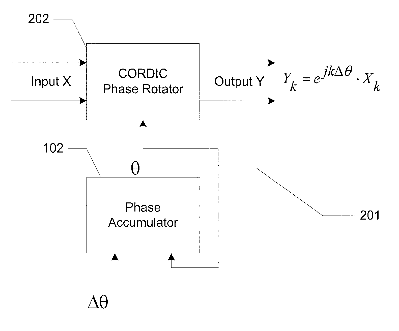
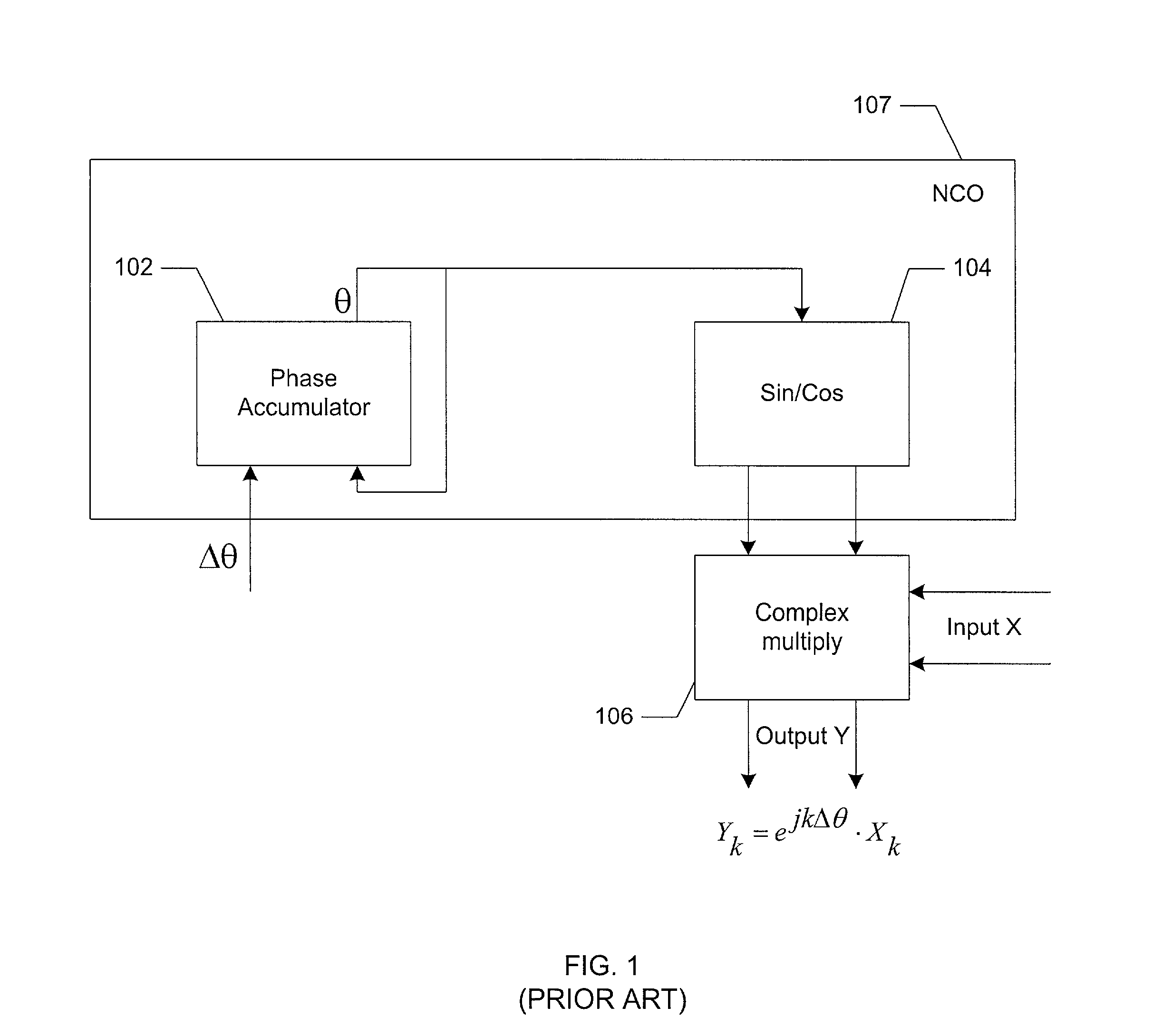
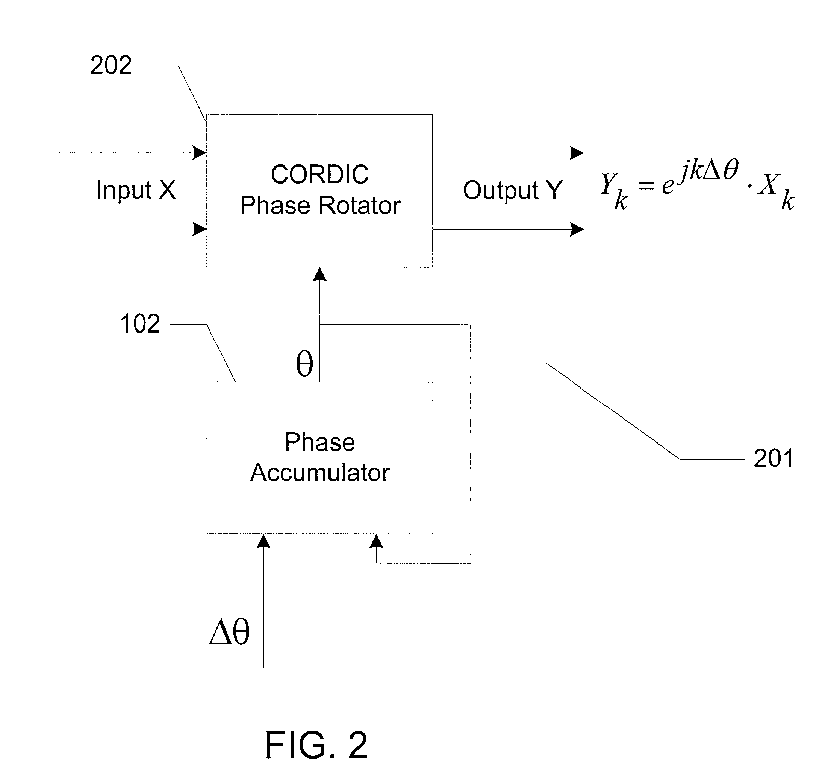
[0026]FIG. 2 is a schematic diagram of a frequency translator 201 according to the present invention. In FIG. 2 phase accumulator 102 outputs a phase angle to a CORDIC phase rotator 202. CORDIC phase rotator rotates an input X by a phase angle θ. The output Y can be expressed as Yk=ejkΔθ·Xk, which is equivalent to the output of conventional frequency translators. However, in frequency translator 201 of the present invention, sin / cos table 104 and complex multiplier 106 are replaced by CORDIC phase rotator 202.

[0027]The Coordinate Rotation Digital Computer (CORDIC) is a well-known algorithm, which was developed in the 1950s, and is described in Andraka, Ray, “A survey of CORDIC algorithms for FPGA based computers,” Proceedings of the 1998 ACM / SIGDA 6th International symposium on FPGAs, Feb. 22–24, 1998, Monterey, Calif, pp. 191–200. The advantage of CORDIC phase rotator 202 is that it uses discrete logic rather than multipliers and lookup tables as required for operation of NCOs. Thu...

second embodiment

[0032]FIG. 3 is a frequency translator according to the present invention using a 14-stage CORDIC phase rotator. An input vector X is to be rotated by a phase angle θ. The inphase (I) and quadrature (Q) components of input vector X are input to a CORDIC phase rotator 302. In the preferred embodiment, CORDIC phase rotator 302 comprises 14 stages, stage 1 through stage 14 . Stages 2 through 14 input the inphase and quadrature components of a vector rotated by the previous stage and output a vector rotated in according to the relation θk=tan−1(2−k) where k is the stage number and θk is the amount of rotation provided by that stage. If θk is negative, the angle is rotated in the negative direction for that stage. In addition, each of these stages outputs an adjusted phase angle. The phase angle is adjusted to account for the rotation provided by that stage. This can be either a positive or negative adjustment depending on the sign of the phase angle input to the stage. For example, if t...


PUM


Abstract

A frequency translator uses a CORDIC phase rotator coupled to a phase accumulator to translate an input signal in frequency. The CORDIC phase rotator performs required phase angle rotations of input vectors using only shift and add operations. Thus, the frequency translator can be readily implemented in hardware. Higher precision arithmetic is used in the CORDIC phase rotator operations than the input vectors contain. To avoid truncation error at the output of the CORDIC phase rotator, stochastic rounding is employed. A dither signal is added to avoid errors due to nonlinear operation of D/A converters, where D/A conversion of the frequency translated signal is required.

Description

[0001]This application claims the benefit of U.S. Provisional Application No. 60 / 223,972, filed Aug. 9, 2000.BACKGROUND[0002]1. Field of the Invention[0003]The present invention relates generally to frequency translation. More specifically, the present invention relates to frequency translation in a communication system that can be easily implemented in digital hardware. The present invention further relates to use of frequency translators in numerous applications, including upconverting baseband signals to RF frequencies for transmission through modems, correcting for local oscillator offsets and FSK modulation.[0004]2. Background of the Invention[0005]Frequency translation is required for numerous applications. For example, transmission of a baseband signal through a modem requires that the baseband signal be upconverted to a suitable transmission frequency. For another example, in wireless modem applications, suitable transmission frequencies are in the RF range. RF synthesizers ...

Claims


Application Information

Patent Timeline
Patent Type & Authority Patents(United States)
IPC IPC(8): H04B1/38H03D7/00H03C3/40H04L27/12
CPCH03C3/40
Inventor SULLIVAN, MARK C.
Owner SKYBITZ INC
Why Eureka
Try Eureka