Piezoelectric electroacoustic transducer and manufacturing method of the same

Inactive Publication Date: 2006-03-28
MURATA MFG CO LTD
View PDF13 Cites 52 Cited by
  • Summary
  • Abstract
  • Description
  • Claims
  • Application Information

AI Technical Summary

Benefits of technology

[0011]In order to overcome the problems described above, preferred embodiments of the present invention provide a piezoelectric electroacoustic transducer and a manufac

Problems solved by technology

However, when using a circular diaphragm, there has been a problem of low production efficiency, low acoustic conversion efficiency, and moreover, difficulty in miniaturizing the piezoelectric electroacoustic transducer.
In this case, it may be difficult to insert-mold because of the complexity of the terminal configuration and it may be difficult to form a fillet for soldering because of a small area of the terminal exposed on the side surface of the ca

Method used


Image

  • Piezoelectric electroacoustic transducer and manufacturing method of the same
  • Piezoelectric electroacoustic transducer and manufacturing method of the same
  • Piezoelectric electroacoustic transducer and manufacturing method of the same

Examples


Embodiment Construction

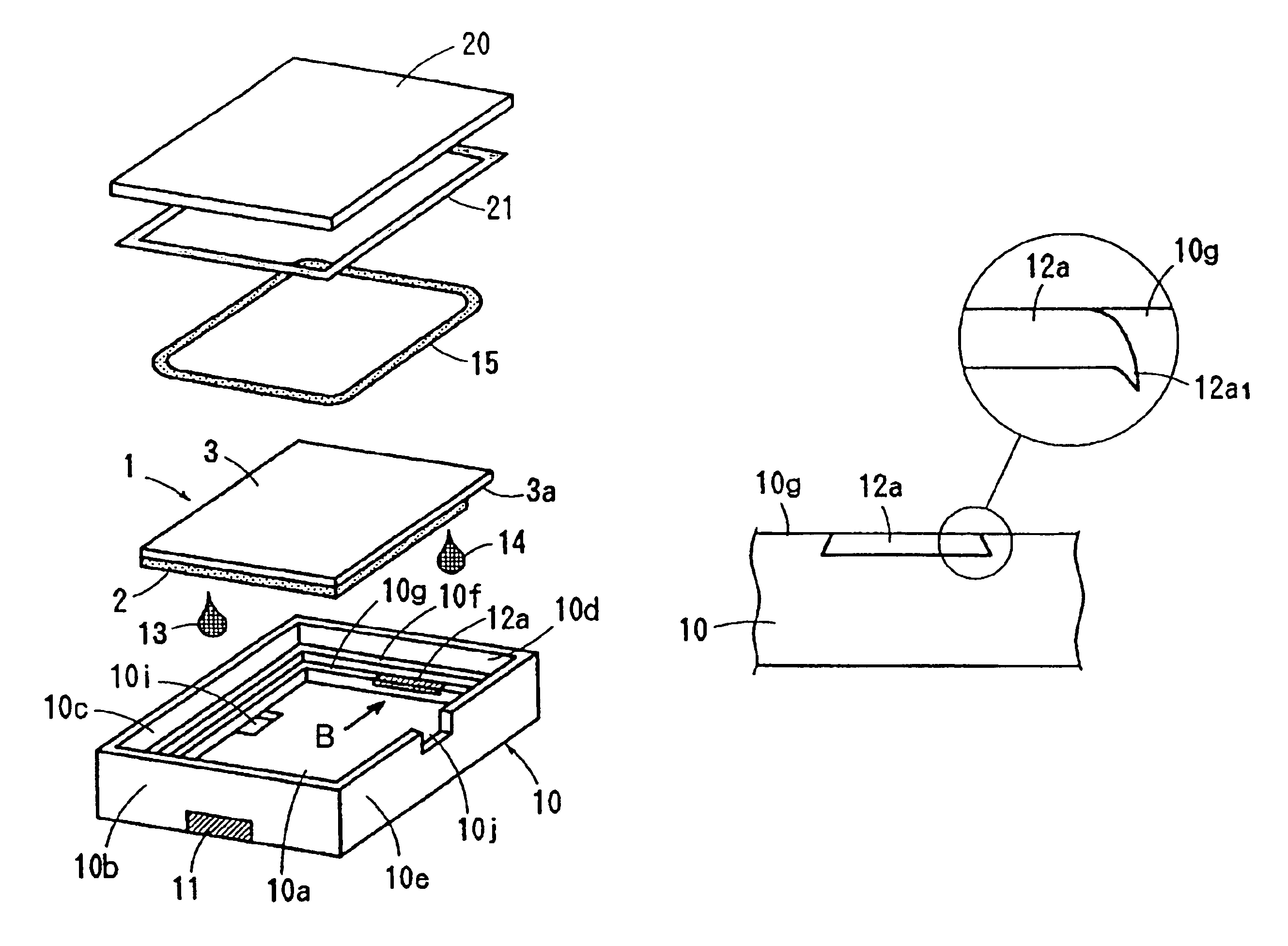
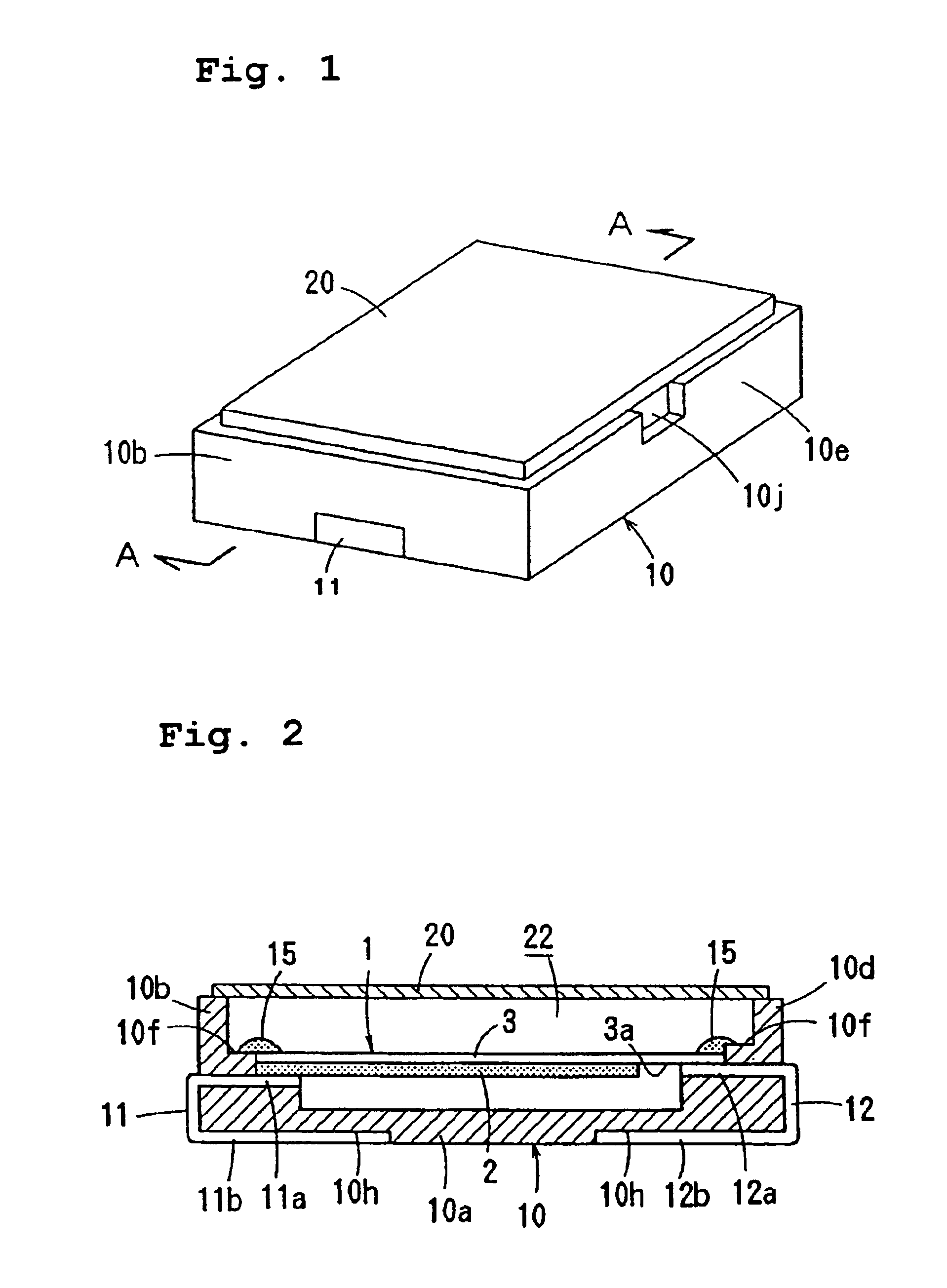
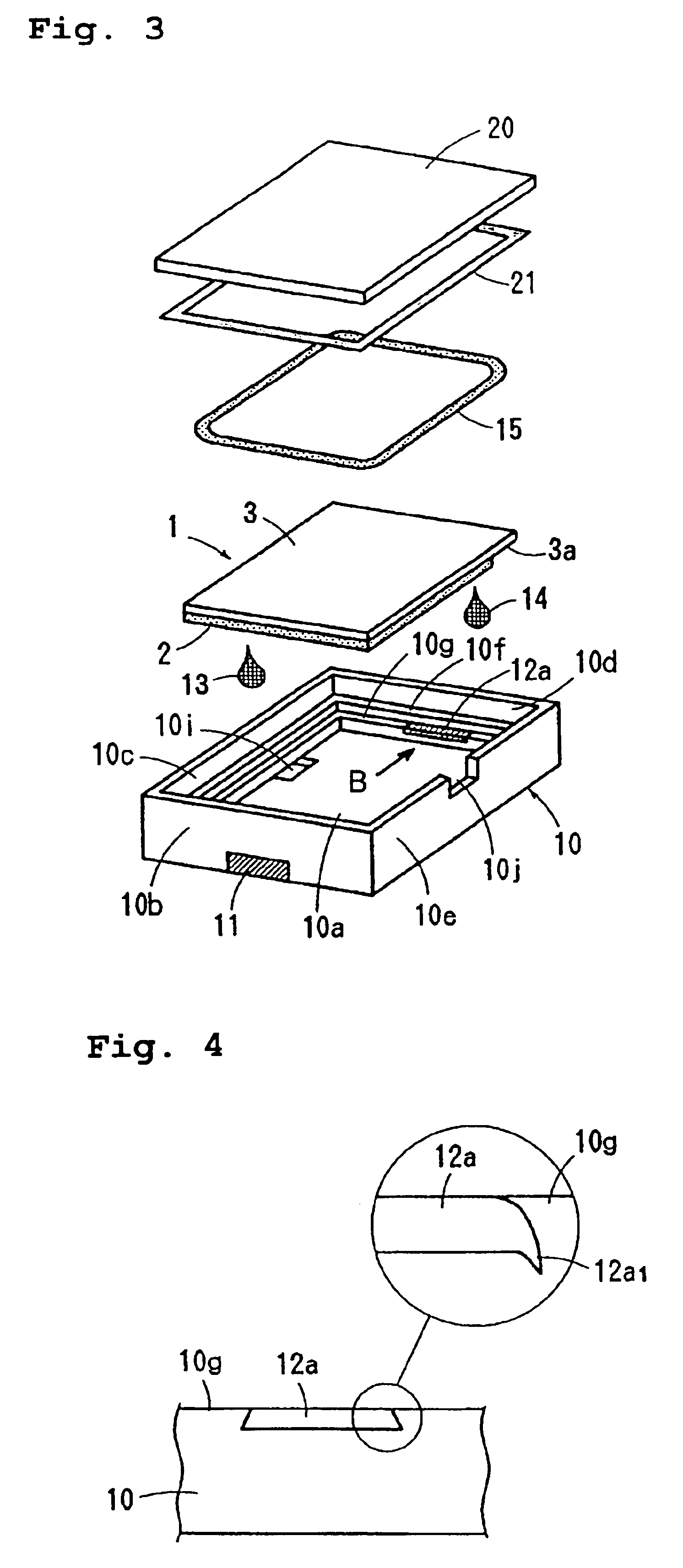
[0028]FIGS. 1 to 4 show a surface-mount sounder that is an example of a piezoelectric electroacoustic transducer according to preferred embodiments of the present invention.

[0029]The piezoelectric electroacoustic transducer preferably includes a unimorph-type piezoelectric diaphragm 1, a case 10, and a lid plate 20.

[0030]The diaphragm 1, as shown in FIG. 5, includes a substantially rectangular piezoelectric plate 2, which is polarized in the thickness direction and has thin-film or thick-film electrodes 2a and 2b respectively disposed on top and back surfaces thereof, and a substantially rectangular metallic plate 3 with substantially the same width as that of the piezoelectric plate 2 and with a slightly longer length than that thereof, which is faced and bonded on the back-surface electrode 2b of the piezoelectric plate 2 via a conductive adhesive or other suitable material. In addition, the metallic plate 3 may be directly joined to the back surface of the piezoelectric plate 2 v...


PUM


Abstract

A piezoelectric electroacoustic transducer includes a substantially rectangular piezoelectric diaphragm having electrodes and flexurally vibrating in response to application of an alternating signal between the electrodes, a resin case having a supporting member disposed inside sidewalls of the case for supporting the diaphragm, terminals insert-molded in the case so as to have internal connections exposed in the supporting member and external connections exposed on the external surface of the case, a conductive adhesive for electrically connecting the electrodes of the diaphragm to the internal connections of the terminals, an elastic sealant for sealing a gap between the external periphery of the diaphragm and the internal periphery of the case, and a lid plate for closing an opening of the case. The terminals are pressed terminals, which are made by punching a metallic plate so that a flash-producing surface is to be the lower surface, and flashes on both respective side-edges of the internal connections are embedded inside the supporting member of the case so that the top surfaces of the internal connections are flush with the surface of the supporting member, and the external connections of the terminals are bent toward the bottom surface of the case via the side surfaces thereof.

Description

BACKGROUND OF THE INVENTION[0001]1. Field of the Invention[0002]The present invention relates to a piezoelectric electroacoustic transducer that is suitable for surface mounting and a manufacturing method thereof, and in particular relates to a structure of terminals thereof.[0003]2. Description of the Related Art[0004]In electronic devices, electronic home appliances, portable telephones, and other such electronic devices, piezoelectric electroacoustic transducers have been widely used as a piezoelectric buzzer or piezoelectric receiver for producing an alarm sound or an operating sound. A piezoelectric electroacoustic transducer of this type generally includes a circular piezoelectric element bonded to one surface of a circular metallic plate to form a unimorph-type diaphragm, and the periphery of the metallic plate is mounted on a circular case using silicone rubber while an opening of the case is closed with a cover.[0005]However, when using a circular diaphragm, there has been ...

Claims


Application Information

Patent Timeline
IPC IPC(8): H04R25/00H04R17/10B06B1/06G10K9/122H01L41/09H04R17/00
CPCB06B1/0603H04R17/00
Inventor HAMADA, KAZUAKIFUJINO, MASAYUKI
Owner MURATA MFG CO LTD
Why Eureka
Try Eureka