
Apparatuses, devices, systems and methods employing far infrared radiation and negative ions

a technology of applied in the field of apparatuses, devices, systems and methods employing far infrared radiation and negative ions, can solve the problems of negative ion technology, increased costs associated with those processes, and inability to emit negative ions at room temperature, so as to improve water purification processes, improve fuel or natural gas processes, and reduce emissions

Inactive Publication Date: 2006-04-04
SLINGO FRED M
View PDF32 Cites 23 Cited by
  • Summary
  • Abstract
  • Description
  • Claims
  • Application Information

AI Technical Summary

Benefits of technology

[0025]An advantage of the present invention is to provide devices, apparatuses, systems and methods that employ material that radiate FIR and material that emits negative ions.
[0026]Another advantage of the present invention is to provide devices, apparatuses, systems and methods that employ material that is capable of emitting both FIR and negative ions.
[0027]Still another advantage of the present invention is the enhancement of fuel or natural gas processes with a substance capable of emitting FIR and negative ions or substances which together emit negative ions and FIR.
[0028]Still yet another advantage of the present invention is to provide improved water purification processes that employ material that emits FIR and negative ions or a combination of material that together emit FIR and negative ions.
[0029]A further advantage of the present invention is to provide devices, apparatuses, systems and methods that can reduce emissions produced during fuel combustion processes.
[0030]A still further advantage of the present invention is to provide devices, apparatuses, systems and methods that can enhance the fuel efficiency of fuel combustion processes.

Problems solved by technology

However, typical bio-ceramic materials do not emit negative ions at room temperature and are generally limited in their ability to do so unless subject to temperatures exceeding about 1000° F.
However, the application of negative ion technology can be problematic due to, for example, the fact that the application of the technology typically can require extensive modifications to existing processes, thus increasing costs associated with those processes.

Method used


Image

  • Apparatuses, devices, systems and methods employing far infrared radiation and negative ions
  • Apparatuses, devices, systems and methods employing far infrared radiation and negative ions
  • Apparatuses, devices, systems and methods employing far infrared radiation and negative ions

Examples


example 1

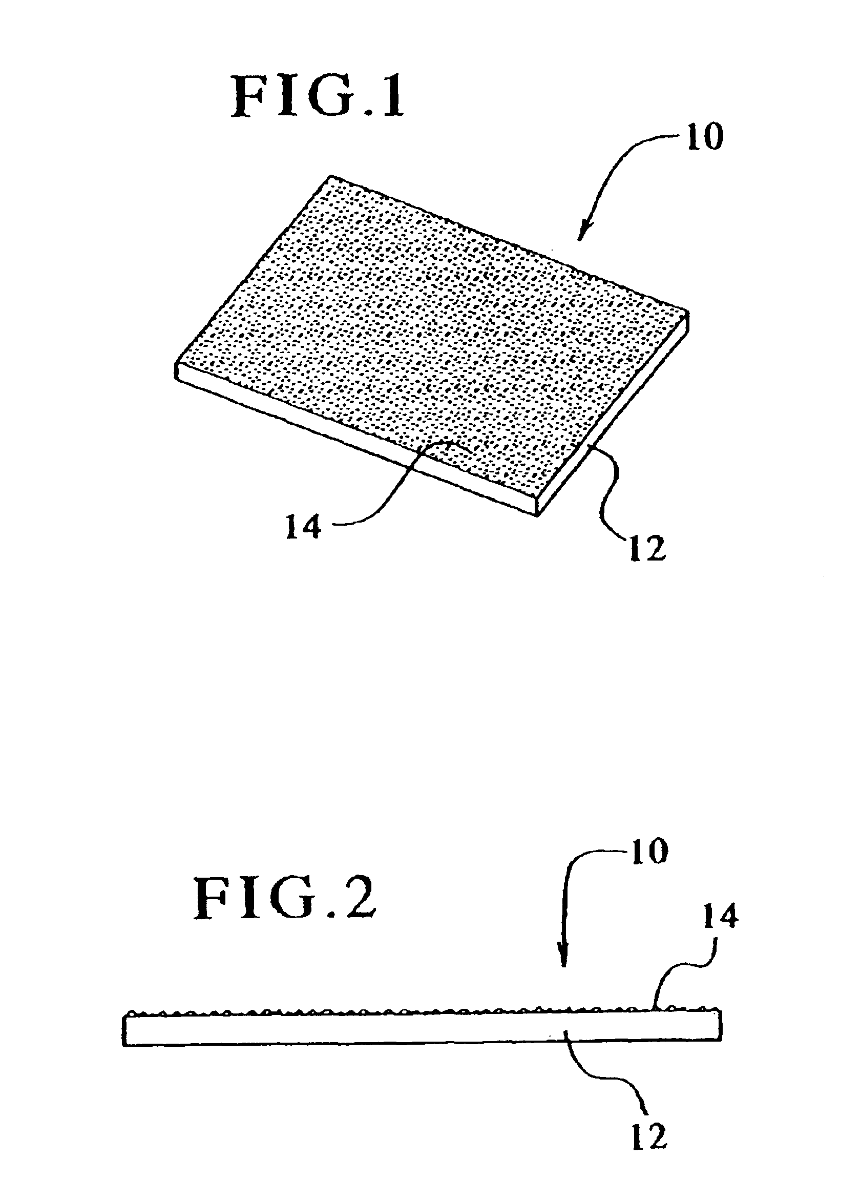
[0070]A FIR / Negative ion emitting ceramic material in the form of a powder was adhered to a piece of elasticized fabric. The fabric was wrapped around and secured to a fuel line of a motor vehicle, thus allowing the material to substantially contact the exterior of a portion of the fuel line. The elasticized fabric device was secured in place with Velcro™ straps according to an embodiment of the present invention. The motor vehicle used for this test was a 2003 Acura 3.2L TL Type S.

[0071]The motor vehicle was road tested over a period of about one and half months. As indicated below in Table 1, the fuel consumption was measured after driving a certain amount of miles to determine the fuel efficiency in miles per gallon (“MPG”): [t1]

[0072]

TABLE 1AMilesGallonsMPG165.47.08223.35183.67.2225.429173.48.0321.59154.17.2221.343229.411.0320.797210.99.4122.41142.86.7321.218259.710.3725.043226.510.9820.628

[0073]This test was conducted using the same type of gasoline from the same gas station. T...

example 2

[0074]The FIR / negative ion emitting material of the present invention was tested to demonstrate its effectiveness on the reduction of exhaust emissions. A FIR / negative ion emitting material was coupled to the fuel line of a motor vehicle similar to the FIR / negative ion emitting material of Example 1 pursuant to an embodiment of the present invention. The motor vehicle used for this test was a 1986 Honda Accord with a 2.0 Liter, 4 cylinder engine and automatic transmission. The emission tests were conducted at a certified emission test station in Illinois. The car was initially emission tested without the FIR / negative ion emitting material. At that time, the recorded mileage for the car was about 237,000. The FIR / negative ion emitting material was then coupled to the fuel line of the car as discussed above and again emission tested. The results of the emission tests are indicated below in Table 2A. [t2]

[0075]

TABLE 2AFIR / Negative IonTestInitialEmitting MaterialCO Emissions Reading (3....

example 3

[0077]A FIR / Negative ion emitting ceramic material in the form of a powder was adhered to a piece of elasticized fabric. The fabric was wrapped around and secured to a water supply line, thus allowing the material to substantially contact the exterior of a portion of the supply line. The elasticized fabric device was secured in place with Velcro™ straps according to an embodiment of the present invention.

[0078]Prior to securing the device of the present invention to the water supply line, the alkalinity and redox potential of the water was measured as being 7.21 pH and +86, respectively. Following securing the device of the present invention to the water supply line, the alkalinity and redox potential of water passing through the line was immediately measured as being 8.3 Ph and −61, respectively. After several hours, the alkalinity and redox potential measurements of the water stabilized at 8.8 pH and −100, respectively.


PUM

PropertyMeasurementUnit
wavelengthaaaaaaaaaa
temperaturesaaaaaaaaaa
timeaaaaaaaaaa

Abstract

Apparatuses, devices, systems and methods employing a material or combination of materials capable of emitting both far infared radiation and negative ions are provided. The material at least include a first part of, for example, a bio-ceramic, and a second part that includes an additional oxide material. The material can be used in a variety of different applications including, for example, internal engine combustion, natural gas combustion, water purification or the like.

Description

CROSS REFERENCE TO RELATED APPLICATIONS[0001]This patent application is a continuation-in-part of U.S. Pat. application Ser. No. 10 / 213,197, filed on Aug. 5, 2002 now abandoned herein incorporated by reference.BACKGROUND OF THE INVENTION[0002]Far infrared radiation (FIR) commonly refers to electromagnetic radiation that has a wave length between the visible light region and the microwave region of the electromagnetic spectrum. In general, FIR or other like terms as used herein refers to electromagnetic radiation that has a wavelength ranging from about 5.6 microns to about 1000 microns.[0003]Certain types of ceramics containing silica oxide and aluminum oxide are known to radiate FIR at room temperature, and to radiate elevated levels of FIR when heated. For example, some types of these ceramics are commonly referred to as bio-ceramics because of reported biological and physiological effects attributed to such materials.[0004]However, typical bio-ceramic materials do not emit negati...

Claims


Application Information

Patent Timeline
Patent Type & Authority Patents(United States)
IPC IPC(8): F02B51/00B01D53/00B01J19/12B01J19/24C02F1/30F01N3/08F02M27/06
CPCB01D53/007B01J19/128B01J19/2485F02M27/06C02F1/30F01N3/08B01J2219/0875B01J2219/0892B01J2219/0877
Inventor SLINGO, FRED M.
Owner SLINGO FRED M
Learn More