Field weakening motor control system and method

a field weakening and control system technology, applied in the direction of electronic commutation motor control, motor/generator/converter stopper, dynamo-electric converter control, etc., can solve the problem of poor dynamic performance of voltage control loop approach, inability to guarantee the optimum torque per ampere in the field-weakening region, and the current angle control loop approach cannot work with high-back emf pm machines. to achieve the effect of improving stability

Inactive Publication Date: 2006-04-04
GM GLOBAL TECH OPERATIONS LLC
View PDF17 Cites 51 Cited by
  • Summary
  • Abstract
  • Description
  • Claims
  • Application Information

AI Technical Summary

Benefits of technology

[0006]A flux weakening module for a permanent magnet electric machine includes a feedforward stator flux term and a compensating feedback flux correction term. The feedforward stator flux term provides the dominant field weakening flux value. The feedback flux correction term improves stability under dynamic conditions and compensates for parameter variations in steady-state. These two flux terms are added and limited to provide the final stator flux command.

Problems solved by technology

Inherently, the voltage control loop approach has poor dynamic performance.
Additionally, for IPM machines with reluctance and magnet flux, using the voltage control loop for field weakening does not guarantee optimum torque per ampere in the field-weakening region.
The current angle control loop approach does not work with high back EMF PM machines since it cannot inject any field weakening current when torque is not applied at higher speeds.
In addition, for a given constant torque command, the current angle control loop approach will not maintain constant developed torque (i.e. torque linearity) as the drive enters into field weakening and approaches maximum speed.

Method used


Image

  • Field weakening motor control system and method
  • Field weakening motor control system and method
  • Field weakening motor control system and method

Examples


Embodiment Construction

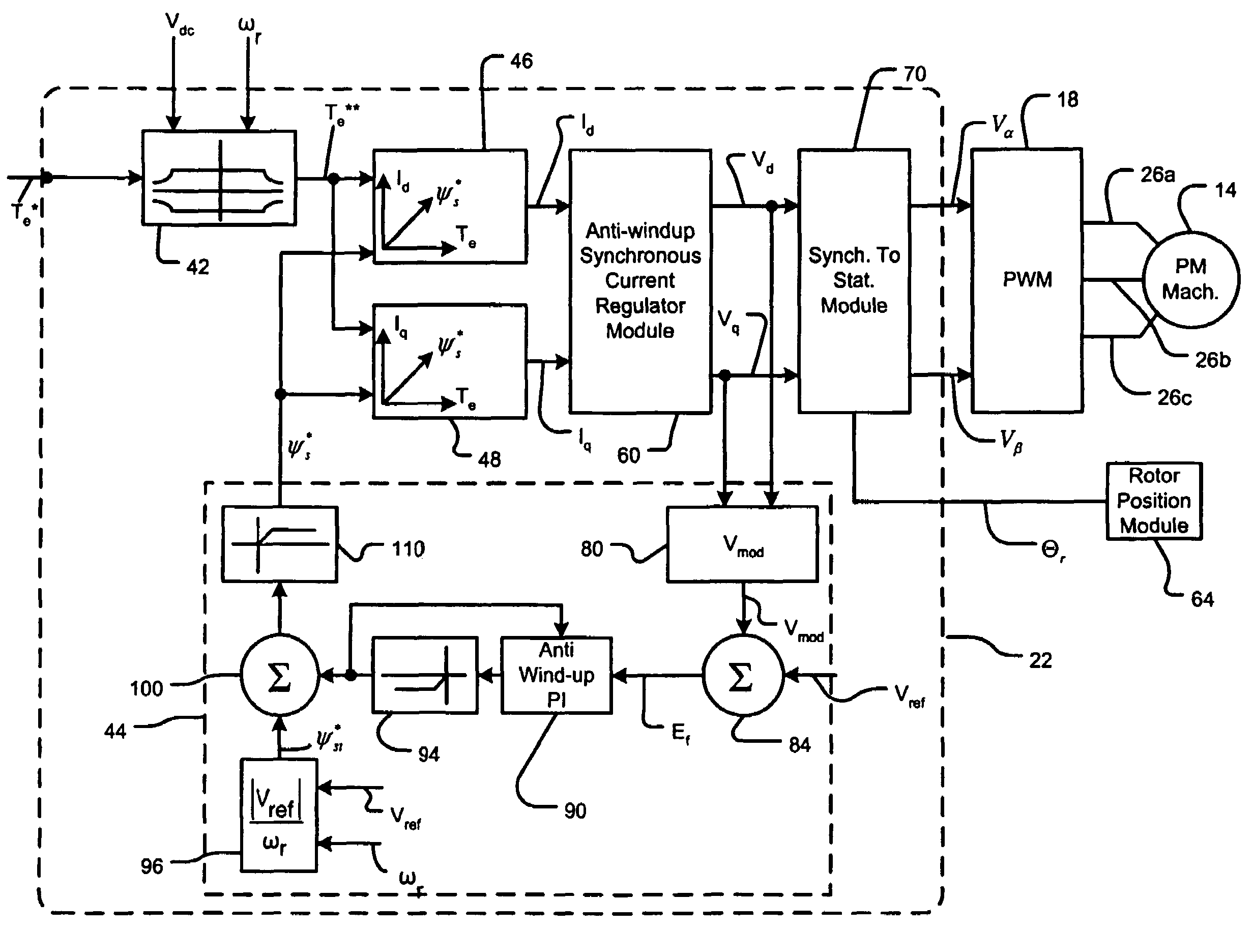
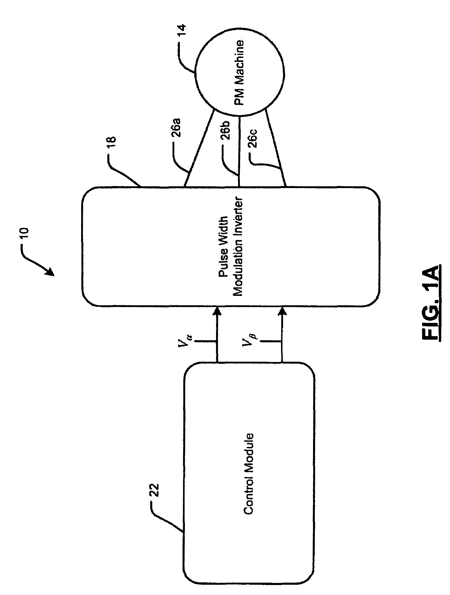
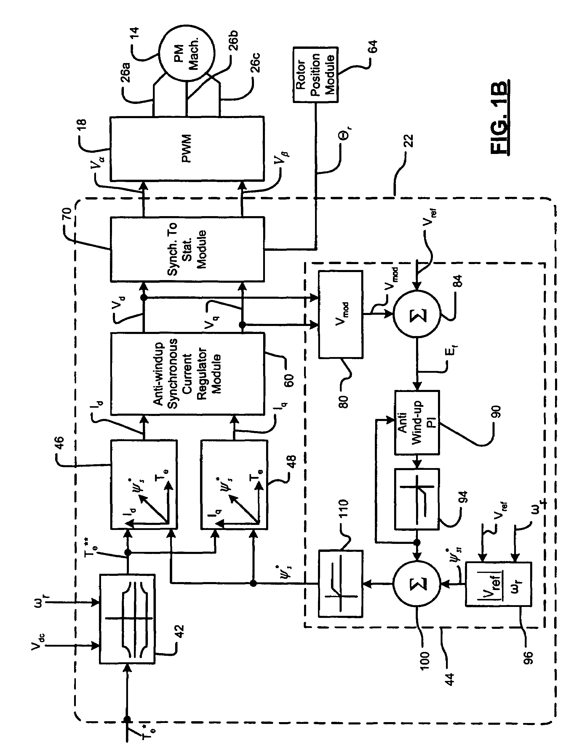
[0021]The following description of the preferred embodiment(s) is merely exemplary in nature and is in no way intended to limit the invention, its application, or uses. As used herein, the term module refers to an application specific integrated circuit (ASIC), a controller, an electronic circuit, a processor (shared, dedicated, or group) and memory that execute one or more software or firmware programs, a combinational logic circuit, or other suitable components that provide the described functionality.

[0022]The voltage equation for the IPM in the synchronous rotating reference frame can be represented in matrix form as follows:

[0023][VdseVqse]=[Rs-ωe⁢⁢Lqsωe⁢⁢LdsRs]⁡[idseiqse]+[0ωe⁢⁢ϕf](1)

Vdse and Vqse are d-axis and q-axis motor terminal voltages in the synchronous reference frame. idse and iqse are d-axis and q-axis motor terminal currents in the synchronous reference frame. Lds and Lqs are d-axis and q-axis stator self-inductances. Rs is stator resistance. φf is the permanent ma...


PUM


Abstract

A control system for an electric machine includes a flux weakening module, which includes a voltage magnitude calculator that receives d-axis and q-axis command voltages and that generates a voltage magnitude. An error circuit compares the voltage magnitude to a reference voltage and generates an error signal. A controller receives the error signal and generates a feedback flux correction signal. A limiter limits the feedback flux correction signal to a predetermined flux value and generates a limited feedback flux correction signal. A feedforward stator flux generating circuit generates a feedforward stator flux signal. A summing circuit sums the feedforward stator flux signal and the limited feedback flux correction signal to generate a final stator flux command.

Description

FIELD OF THE INVENTION[0001]The present invention relates to the control of permanent magnet (PM) motors in both the constant torque and flux weakening regions, and more particularly to adjusting magnetic flux to improve the performance of PM motors beyond a base speed.BACKGROUND OF THE INVENTION[0002]A vector controlled PWM voltage source inverter may be used to excite a PM motor, such as an interior permanent magnet (IPM) motor. Using this approach provides accurate torque control, improved dynamic response, and increased motor efficiency. Reducing the magnetic flux inside the motor, which is also called flux or field weakening, may provide improved power characteristics of the PM motor at higher speeds. Flux weakening in a PM motor can be accomplished by adjusting the stator excitation.[0003]During a constant torque region, closed loop current regulators control the applied PWM voltage excitation so that the instantaneous phase currents follow their commanded values. However, sat...

Claims


Application Information

Patent Timeline
Patent Type & Authority Patents(United States)
IPC IPC(8): H02P3/18H02P3/00
CPCH02P21/10H02P21/0089
Inventor PATEL, NITINKUMAR R.SCHULZ, STEVEN E.SUL, SEUNG KIBAE, BON-HO
Owner GM GLOBAL TECH OPERATIONS LLC
Why Eureka
Try Eureka