Magnetic imaging microscope test system and its application for characterization of read and write heads for magnetic recording

a magnetic recording and test system technology, applied in the field of scanning microscopy, can solve the problems of inability to de-convolve, difficult and in some cases impossible to interpret images, and only work with static magnetic fields, and achieve the effect of extracting the stiffness of the sensor and hard bias properties

Inactive Publication Date: 2006-04-04
IBM CORP
View PDF12 Cites 7 Cited by
  • Summary
  • Abstract
  • Description
  • Claims
  • Application Information

AI Technical Summary

Benefits of technology

[0019]The stimulation mode of operation can be applied for characterization of the sensors of magnetic recording read heads. The magnetic stencil is scanned over the read sensor and driven by an AC current while the response of the sensor, i.e. it's change in resistance, is recorded. By doing so, parameters such as magnetic read track width, amplitude, pulse width at half amplitude (PW50), and position-dependent stability can be determined. By repeating the scans at varied stencil amplitude, position-dependent transfer curves can be obtained, allowing extraction of the sensor stiffness and hard bias properties.

Problems solved by technology

By the way of background, current methods for magnetic imaging suffer from various limitations.
Even though MFM provides high spatial resolution, it does not actually measure magnetic field, but rather the magnetic field gradient, making interpretation of the images difficult and, in some cases, impossible to de-convolute.
Additionally, MFM only works with static magnetic fields and has no time-domain capabilities.
However, Kerr microscopy can only image magnetization of the material, thus limiting the technique in the choice of materials.
Additionally, because Kerr microscopy is an optical technique, the spatial resolution is limited by the wavelength of light.
More recent advances in the field of magnetic imaging, such as Lorenz microscopy, ballistic electron emission microscopy, and polarization X-ray microscopy also suffer from various limitations, and are complicated and expensive.
In addition to being an indirect method of head characterization, these methods involve long evaluation cycles and the high cost associated with building individual sliders.

Method used


Image

  • Magnetic imaging microscope test system and its application for characterization of read and write heads for magnetic recording
  • Magnetic imaging microscope test system and its application for characterization of read and write heads for magnetic recording
  • Magnetic imaging microscope test system and its application for characterization of read and write heads for magnetic recording

Examples


Embodiment Construction

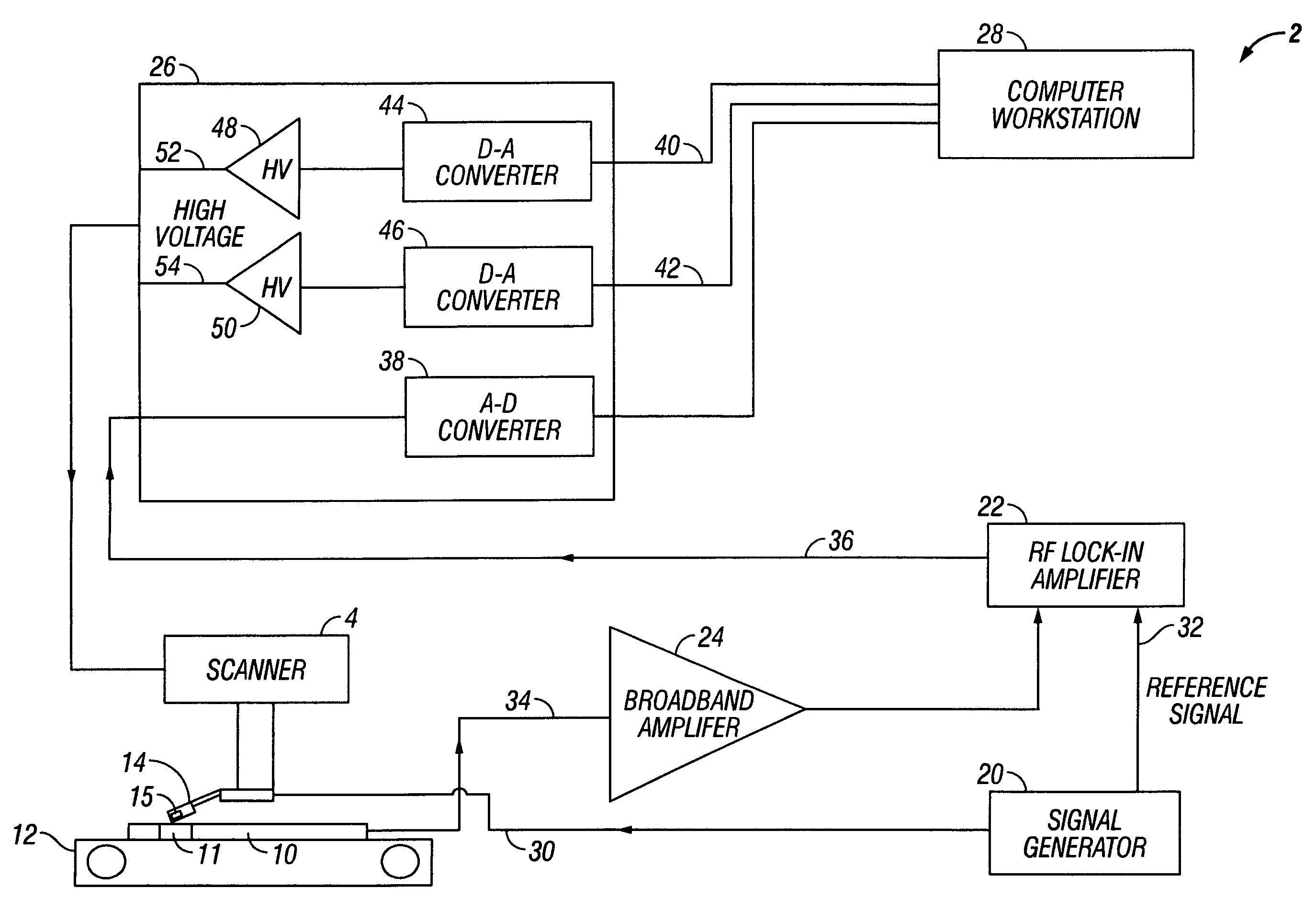
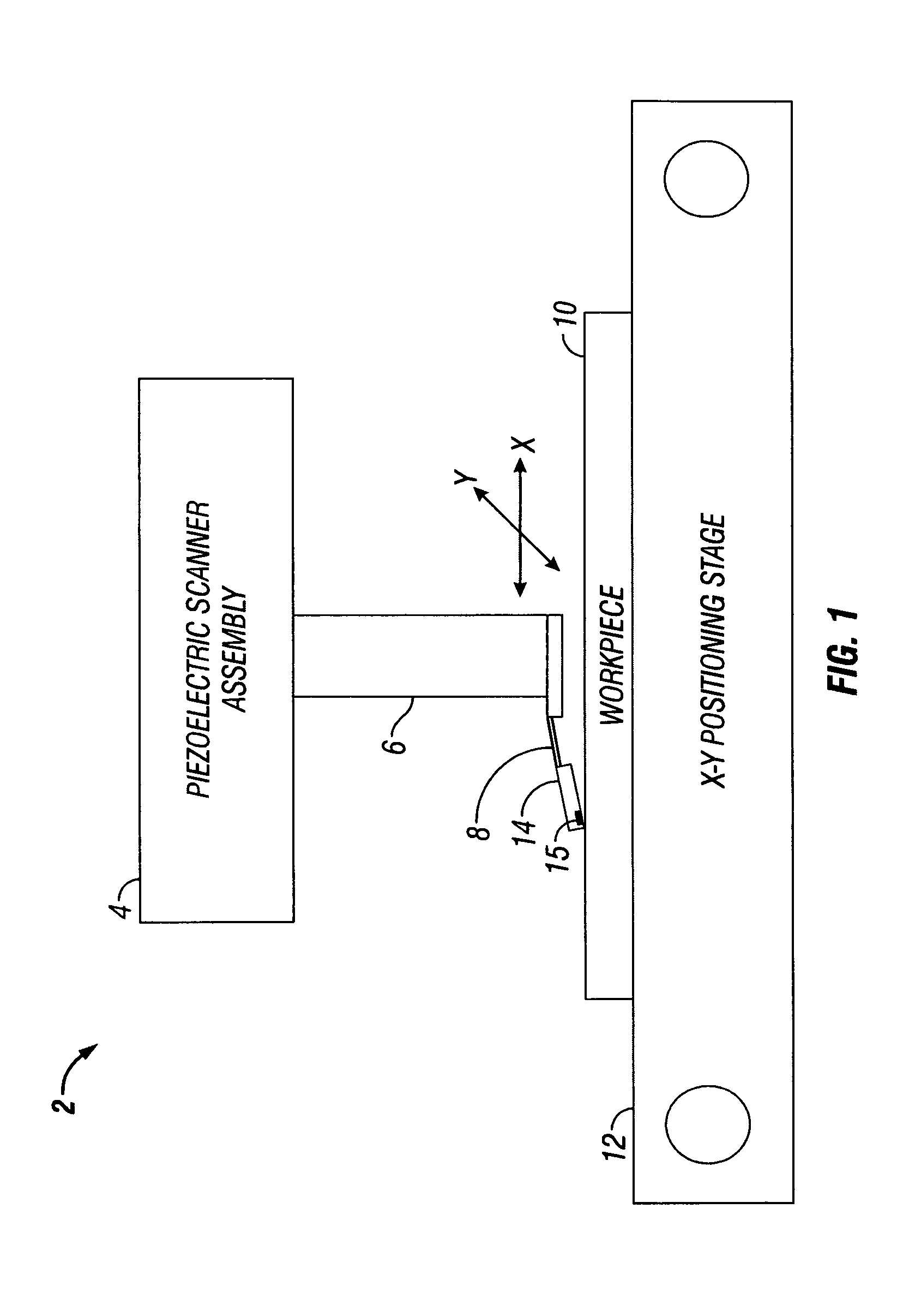
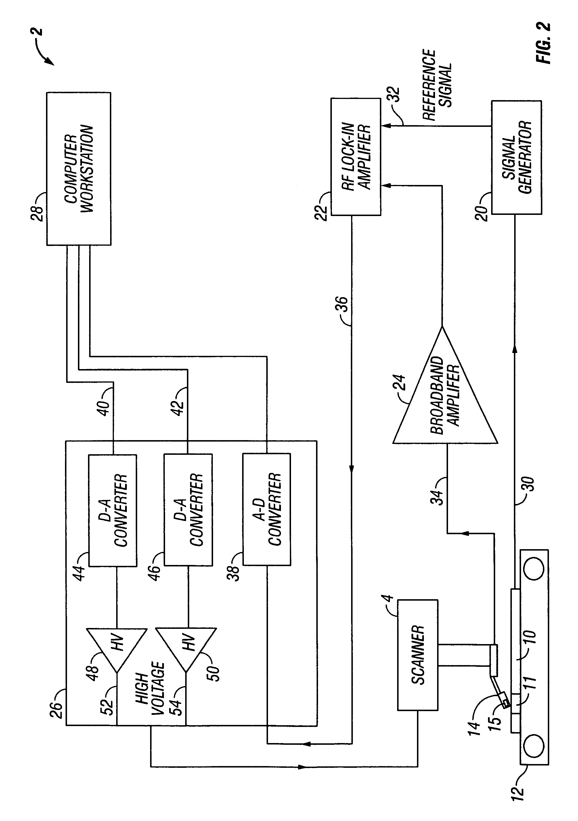
[0043]Turning now to the figures, wherein like reference numerals represent like elements in all of the several views, FIG. 1 illustrates a magnetic imaging microscope test system 2 adapted for high resolution magnetic characterization of magnetic field generating and sensing devices, and particularly disk drive inductive write heads and magnetoresistive read heads. The test system 2 includes a scanner assembly 4 that is preferably adapted for very finely controllable (e.g., ˜1 nm) resolution) two-dimensional movement in the directions shown by the x and y axes in FIG. 1. A conventional piezoelectric control system of the type used in a standard MFM may be used for this purpose. The scanner assembly 4 includes a piezoelectric assembly 6 that carries a probe arm 8. The probe arm 8 is cantilevered from the piezoelectric assembly 6 so as to extend toward a work piece 10. In the context of the present invention, the work piece 10 will comprise a magnetic field generating or sensing devi...


PUM

PropertyMeasurementUnit
time-aaaaaaaaaa
distanceaaaaaaaaaa
stripe heightaaaaaaaaaa

Abstract

A novel magnetic imaging microscope test system with high spatial (1–10 nm) and temporal (˜1 ns) resolution of the magnetic field is disclosed, as well as the system application for characterization of read and write heads for magnetic recording. The test system includes a scanner assembly and a work piece holder for holding a work piece to be tested. The scanner assembly and the work piece holder are positionable relative to each other at very fine resolution during scanning. A probe arm is cantilevered from the scanner assembly to bring a probe head into close proximity to the work piece holder. The probe head is configured scan a work piece in contacting engagement therewith so that a magnetic device on the probe head magnetically interacts with a magnetic field generating or magnetic field sensing device on the work piece. A probe head for use in the test system and a related test method are also disclosed.

Description

BACKGROUND OF THE INVENTION[0001]1. Field of the Invention[0002]The present invention relates to the field of scanning microscopy. More particularly, the invention concerns the non-intrusive magnetic imaging of devices and systems that generate and / or sense magnetic fields, including the magnetic field output of magnetic write heads and the magnetic response of magnetic read heads.[0003]2. Description of the Prior Art[0004]By the way of background, current methods for magnetic imaging suffer from various limitations. The most widespread method is Magnetic Force Microscopy (MFM). Even though MFM provides high spatial resolution, it does not actually measure magnetic field, but rather the magnetic field gradient, making interpretation of the images difficult and, in some cases, impossible to de-convolute. Additionally, MFM only works with static magnetic fields and has no time-domain capabilities. Another wide-spread magnetic imaging method is Kerr microscopy, which does provide time-...

Claims


Application Information

Patent Timeline
Patent Type & Authority Patents(United States)
IPC IPC(8): G01R33/12G01R33/038G11B5/00G11B5/012G11B5/31G11B5/39G11B5/455
CPCB82Y10/00B82Y35/00G01Q10/06G01Q60/54G01R33/0385G11B5/012G11B5/3166G11B5/3173G11B5/3193G11B5/3909G11B5/455G11B2005/3996G11B5/3103G11B2005/001G11B2005/0013G11B2005/0016B82Y25/00
Inventor NIKITIN, VLADIMIRPENTEK, KATALIN
Owner IBM CORP
Why Eureka
Try Eureka