Charging device and image forming apparatus

a charging device and image forming technology, applied in the direction of electrographic process apparatus, instruments, corona discharge, etc., can solve the problems of defective images, rapid degradation of photosensitive bodies, and increase in volume of discharge products adhesion to the surface of photosensitive bodies

Inactive Publication Date: 2006-04-04
FUJIFILM BUSINESS INNOVATION CORP
View PDF16 Cites 24 Cited by
  • Summary
  • Abstract
  • Description
  • Claims
  • Application Information

AI Technical Summary

Benefits of technology

[0014]The present invention has been made in view of the above circumstances and provides a charging device that can suppress excessive electric discharges and uniformly charge a charged object and also an image forming apparatus having such a charging device.
[0021]Thus, with a charging device of the present invention, it is a direct current that is caused to flow through the contact member due to the electric charge on the charged object electrically charged by the charging member and is necessary for controlling the power source. Therefore, it is no longer necessary to detect minute fluctuations of the electric current value of the AC component and directly gauge the electric potential of the surface of the charged object so that the cost of the device can be reduced. Additionally, since the electric current is caused to flow due to the electric charge on the charged object, it is correlated with the electric potential of the surface of the charged object. Thus, as the power source control section controls the power source on the basis of the electric current, it is possible to suppress excessive electric discharges and realize an electrically uniform charging.
[0033]With the above feature of the device of the present invention, the margin that has to be given to the inter-peak threshold voltage when controlling the DC voltage so that the inter-peak voltage of the AC voltage can be held low if compared with a comparable conventional device with which firstly a lowest possible inter-peak threshold voltage at which electric discharges take place uniformly on a stable basis is detected and the AC voltage that is superimposed on the DC voltage of the power source is controlled according to the detected inter-peak threshold voltage. Therefore, it is now possible to suppress excessive electric discharges and realize an electrically more uniform charging. As a result, the charged object is prevented from becoming degraded due to electric discharges and adherence of discharge products to the charged object is minimized.
[0036]With this arrangement, the inter-peak threshold voltage can be detected in a short period of time.
[0056]The transfer member to which a transfer bias voltage is applied is often provided with an ammeter to be used for controlling the transfer bias voltage. Therefore, when the transfer member operates also as the contact member, the ammeter can be used for the purpose of gauging the electric current that is caused to flow due to the electric charge on the photosensitive body to suppress the cost.
[0061]The reading of the ammeter can involve an error when the nipping length at the transfer position changes. However, this arrangement makes the reading of the ammeter more accurate and realizes an electrically more uniform charging.

Problems solved by technology

However, when a voltage obtained by superimposing an AC component on a DC component is applied, there arises a problem that the number of times of ion collisions at the surface of the photosensitive body increases to quickly degrade the photosensitive body rather than when a voltage obtained only by using a DC component is applied without superimposing an AC component.
There also arises a problem that the volume of the discharge products adhering to the surface of the photosensitive body also increases.
The discharge products adhering to the surface of the photosensitive body obstruct the exposure to light of the image to give rise to defective images called deletion (white space on a colored background).
It is known that these problems become remarkable particularly when the inter-peak voltage Vpp of the AC component that is superimposed on the DC component is large.
On the other hand, uneven electric discharges occur when the inter-peak voltage Vpp is too small.
Thus, the problem of early degradation of the photosensitive body and that of defective images due to discharge products are still remarkable.
However, the proposed technique can only reduce variances in the discharge triggering voltage Vth and does not drastically dissolve the problems.
However, it is indispensable for the technique of Patent Document 2 to detect minute fluctuations of the electric current, which is an extremely difficult job, and the problems as pointed out above arise when such fluctuations are missed.
However, a device for directly observing the electric potential of the surface of a photosensitive body can hardly be made compact and hence such a technique cannot be employed in an image forming apparatus that needs to be down-sized.

Method used


Image

  • Charging device and image forming apparatus
  • Charging device and image forming apparatus
  • Charging device and image forming apparatus

Examples


first embodiment

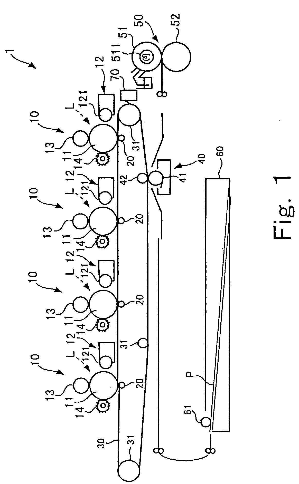
[0103]FIG. 1 is a schematic illustration of the configuration of image forming apparatus according to the invention.

[0104]An image forming apparatus 1 of this embodiment is a full color tandem type image forming apparatus having four toner image forming units that respectively use yellow, magenta, cyan and black toners to form toner images of the respective colors in synchronism with the movement of an intermediary transfer belt. The toner images are laid one on the other on the intermediary transfer belt, which is an intermediary medium (primary transfer) and the image formed on the intermediary transfer belt by sequentially laying the toner images is transferred onto a sheet of paper, which is a recording medium (secondary transfer), and fixed.

[0105]The image forming apparatus 1 of FIG. 1 has four toner image forming units 10, four primary transfer rolls 20, an intermediary semiconductor transfer belt 30 supported by three support rolls 31 and driven to circulate counterclockwise ...

second embodiment

[0152]Now, image forming apparatus according to the invention will be described below.

[0153]As in the case of the image forming apparatus 1 shown in FIG. 1, the image forming apparatus of this embodiment is also a full color tandem type image forming apparatus having four toner image forming units. The component members of the embodiment same as or similar to those of the image forming apparatus 1 of FIG. 1 are denoted respectively by the same reference symbols and only the characteristic parts of the image forming apparatus of the second embodiment will be described below.

[0154]FIG. 14 is a schematic illustration of the characteristic aspects of the configuration of the second embodiment of image forming apparatus.

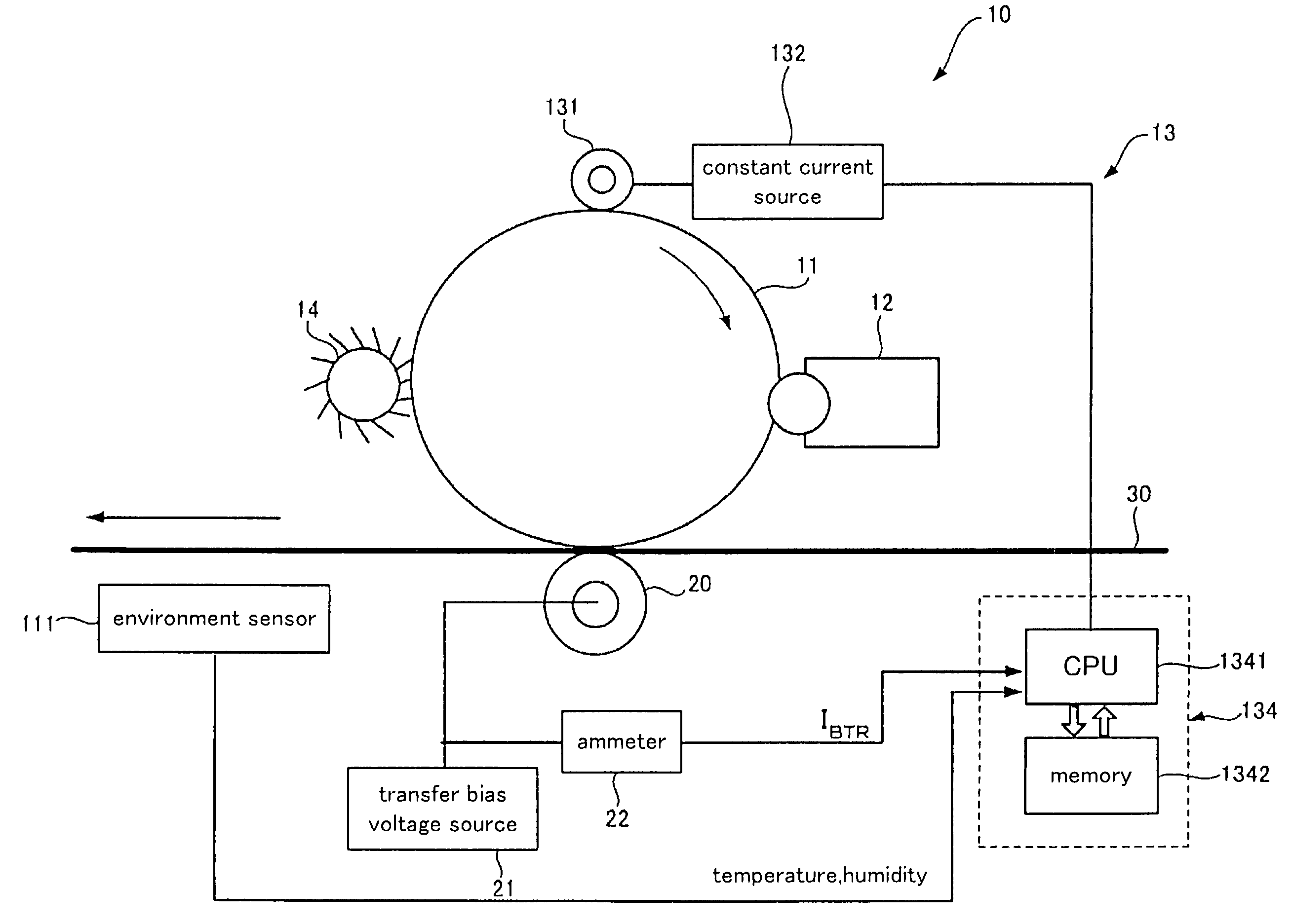
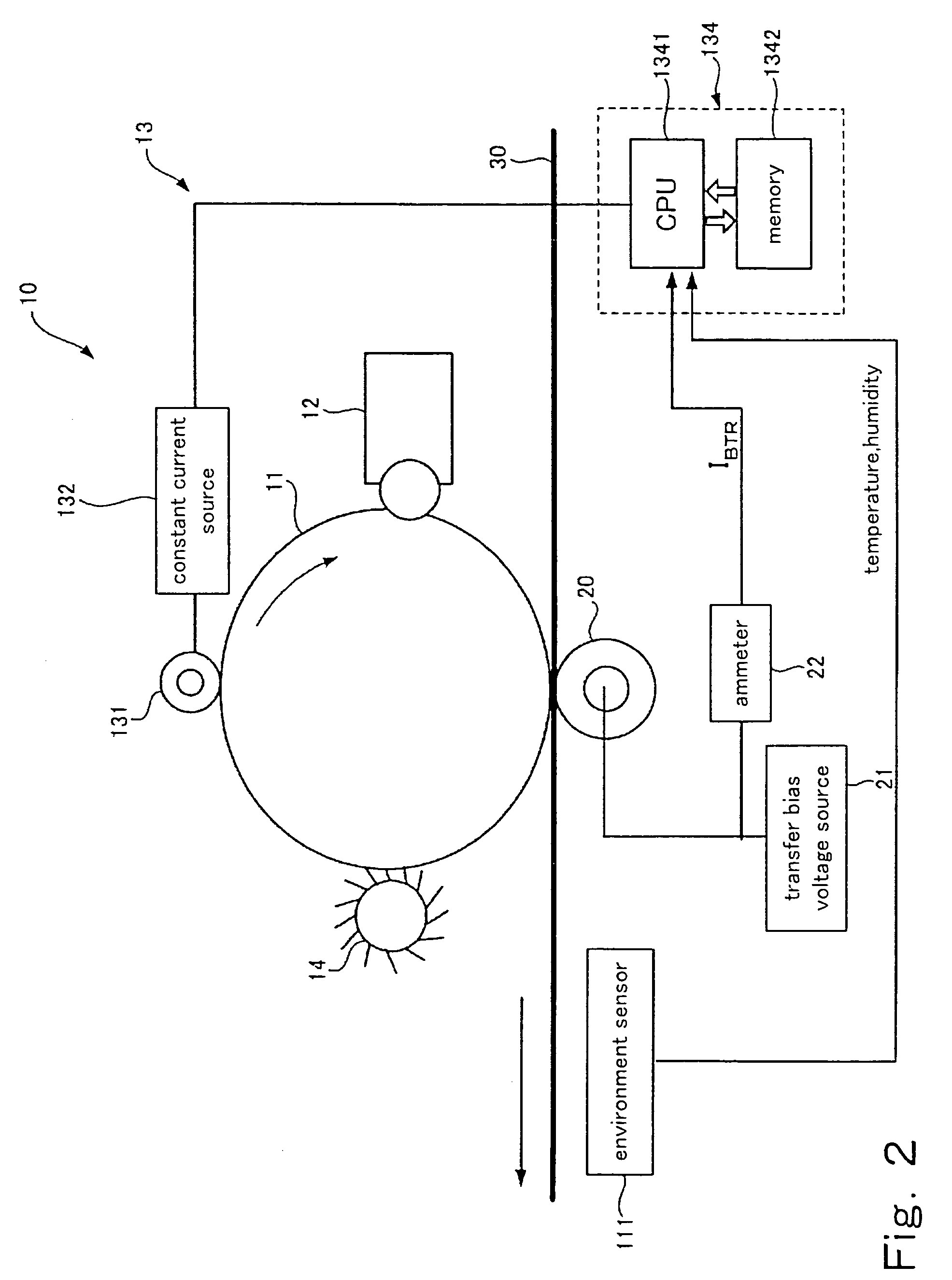
[0155]Like FIG. 2, FIG. 14 shows a toner image forming unit 10 having a photosensitive drum 11, a developing device 12, a contact type charging device 13 and a cleaning brush 14, a primary transfer roll 20 and part of an intermediary transfer belt 30. The second embodimen...

third embodiment

[0168]Now, the present invention will be described below.

[0169]As in the case of the image forming apparatus 1 shown in FIG. 1, the image forming apparatus of this embodiment is a full color tandem type image forming apparatus having four toner image forming units. The component members of the embodiment same as or similar to those of the image forming apparatus 1 of FIG. 1 are denoted respectively by the same reference symbols and only the characteristic parts of the image forming apparatus of the third embodiment will be described below.

[0170]FIG. 16 is a schematic illustration of the characteristic aspects of the configuration of the third embodiment of image forming apparatus.

[0171]Like FIGS. 2 and 12, FIG. 16 shows a toner image forming unit 10, a primary transfer roll 20 and part of an intermediary transfer belt 30. The toner image forming unit 10 shown in FIG. 16 has a photosensitive drum 11, a developing device 12, a contact type charging device 13 and a cleaning brush 14 as...


PUM


Abstract

The present invention is a charging device that electrically charges an object that is charged while being moved in a predetermined direction and an image forming device having such a charging device. The charging device has: a charging member that electrically charges the charged object; a power source that supplies electric power to the charging member in order to electrically charge the charged object; a contact member arranged downstream relative to the charging member as viewed in the moving direction of the charged object and adapted to contact the charged object directly or by way of a predetermined intermediary medium; an ammeter that gauges an electric current caused to flow through the contact member due to an electric charge on the charged object electrically charged by the charging member; and a power source control section that controls the power source based on the electric current gauged by the ammeter.

Description

BACKGROUND OF THE INVENTION[0001]1. Field of the Invention[0002]This invention relates to a charging device for electrically charging a charged object adapted to be electrically charged while moving in a predetermined direction. It also relates to an image forming apparatus having such a charging device.[0003]2. Related Background Art[0004]Conventionally, in image forming apparatus such as copying machines and printers to which an electrophotography process is applied, an image is formed on a recording medium by electrically charging the surface of a revolving photosensitive body by means of a charging device, exposing the surface of the photosensitive body to light to form an electrostatic latent image on the surface thereof, developing the electrostatic latent image to produce a developed visible image by applying a developing agent, transferring the developed image onto a recording medium such as a sheet of recording paper and fixing the transferred image. Available charging devi...

Claims


Application Information

Patent Timeline
Patent Type & Authority Patents(United States)
IPC IPC(8): G03G15/02G03G15/00
CPCG03G15/0266
Inventor ISHII, YASUTOMOTANAKA, KOYA
Owner FUJIFILM BUSINESS INNOVATION CORP
Why Eureka
Try Eureka