Hydraulic camshaft adjuster for an internal combustion engine

a technology of hydraulic camshaft and internal combustion engine, which is applied in the direction of non-mechanical valves, valve drives, couplings, etc., can solve the problems of increasing manufacturing expenses and achieve the effect of increasing manufacturing expenses and simple manufacturing

Inactive Publication Date: 2006-04-11
DAIMLER AG
View PDF7 Cites 46 Cited by
  • Summary
  • Abstract
  • Description
  • Claims
  • Application Information

AI Technical Summary

Benefits of technology

[0006]An important advantage of the camshaft adjuster according to the invention resides in the fact that its hydraulic fluid supply system is relatively simple to manufacture.
[0007]During the manufacture of the valve housing for the control valve passages are machined into the valve sleeve which extends axially from the camshaft end or, respectively, the threaded end of the clamping bolt up to an oil transfer location to the operating chambers of the camshaft adjuster, the passages being open axial supply grooves cut into the clamping bolt. This can be done already during the manufacture of the unfinished product by an inexpensive forming process. The open pressurized fluid passages are closed by a sleeve extending over the valve housing and covering the open passages. The sleeve extends from the camshaft end or, respectively the threaded end of the clamping bolt at least to the end of the open pressurized fluid passages or over the full length of the valve housing. It is advantageous that therefore no axial bores have to be drilled into the valve housing walls. The drilling of axial bores would result in increased manufacturing expenses. Specifically, it would be necessary to remove any burrs at the intersections of axial and radial bores. In addition, the axial bores could have only very small cross-sections since the walls of the valve housing are relatively thin.
[0009]Preferably, at the outer surfaces of the sleeve there are sealing means which accommodate tolerances and heat transfer differences and which reduce any leakage between the various pressure fluid spaces, as the sealing means seal against the inner body of the camshaft adjuster. These sealing means disposed on the outer surface of the sleeve can be so large that they form with the sleeve and the inner body, an annular space so that it is not necessary to provide the grooves in the inner body which are normally present to provide for the transfer of the pressure fluid from the control valve to the operating chambers of the camshaft adjuster.

Problems solved by technology

The drilling of axial bores would result in increased manufacturing expenses.

Method used


Image

  • Hydraulic camshaft adjuster for an internal combustion engine
  • Hydraulic camshaft adjuster for an internal combustion engine
  • Hydraulic camshaft adjuster for an internal combustion engine

Examples


Embodiment Construction

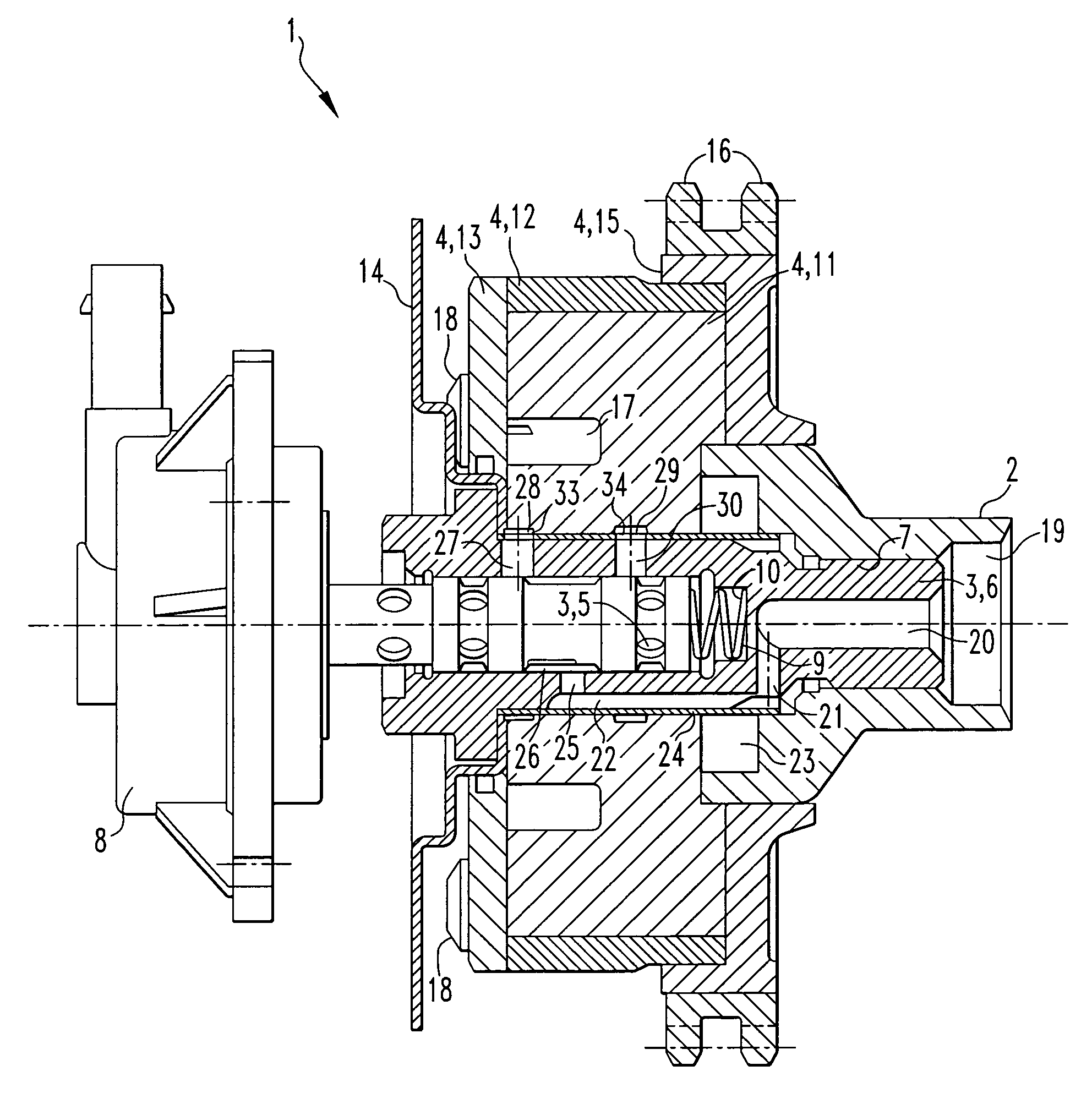
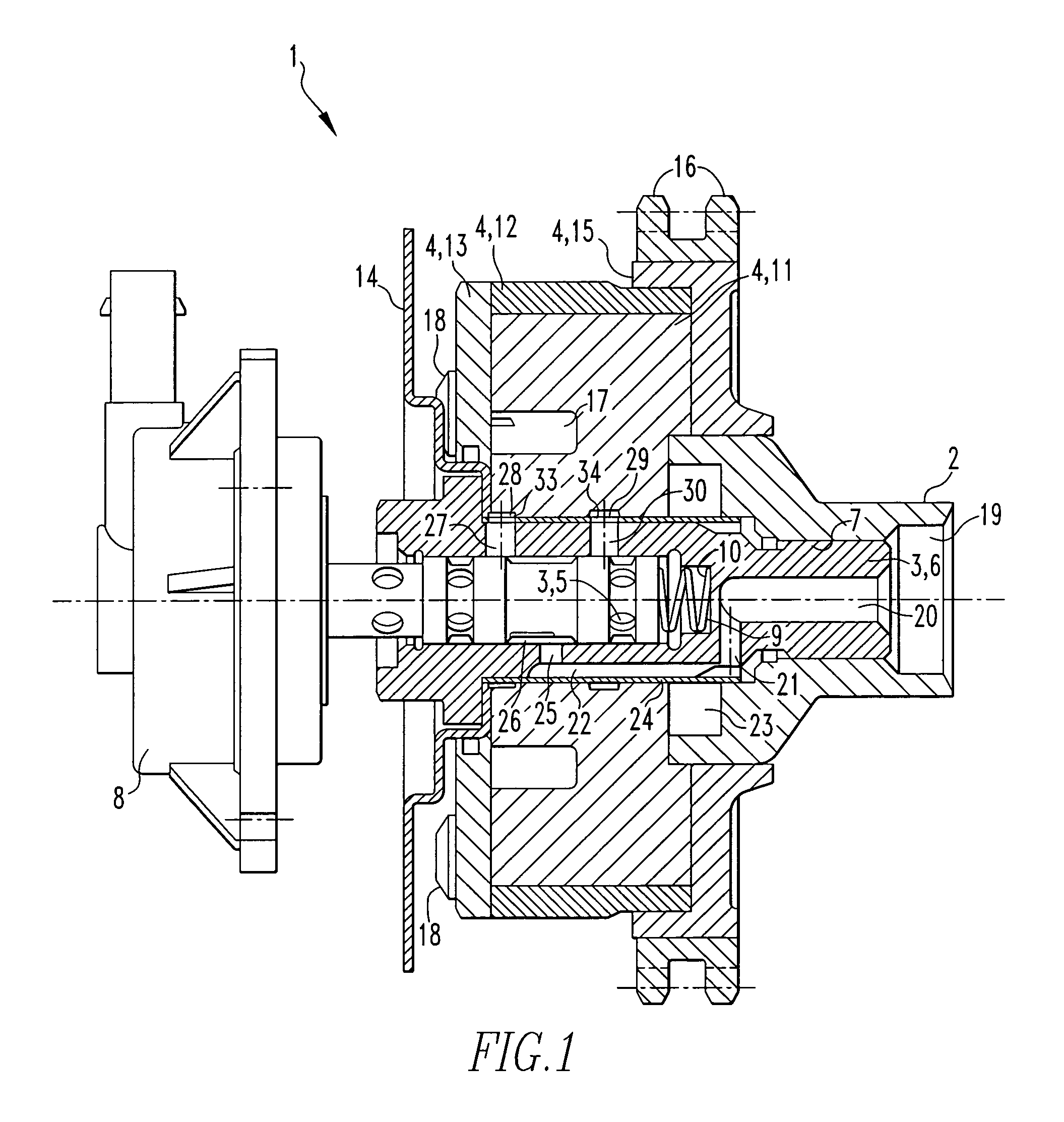
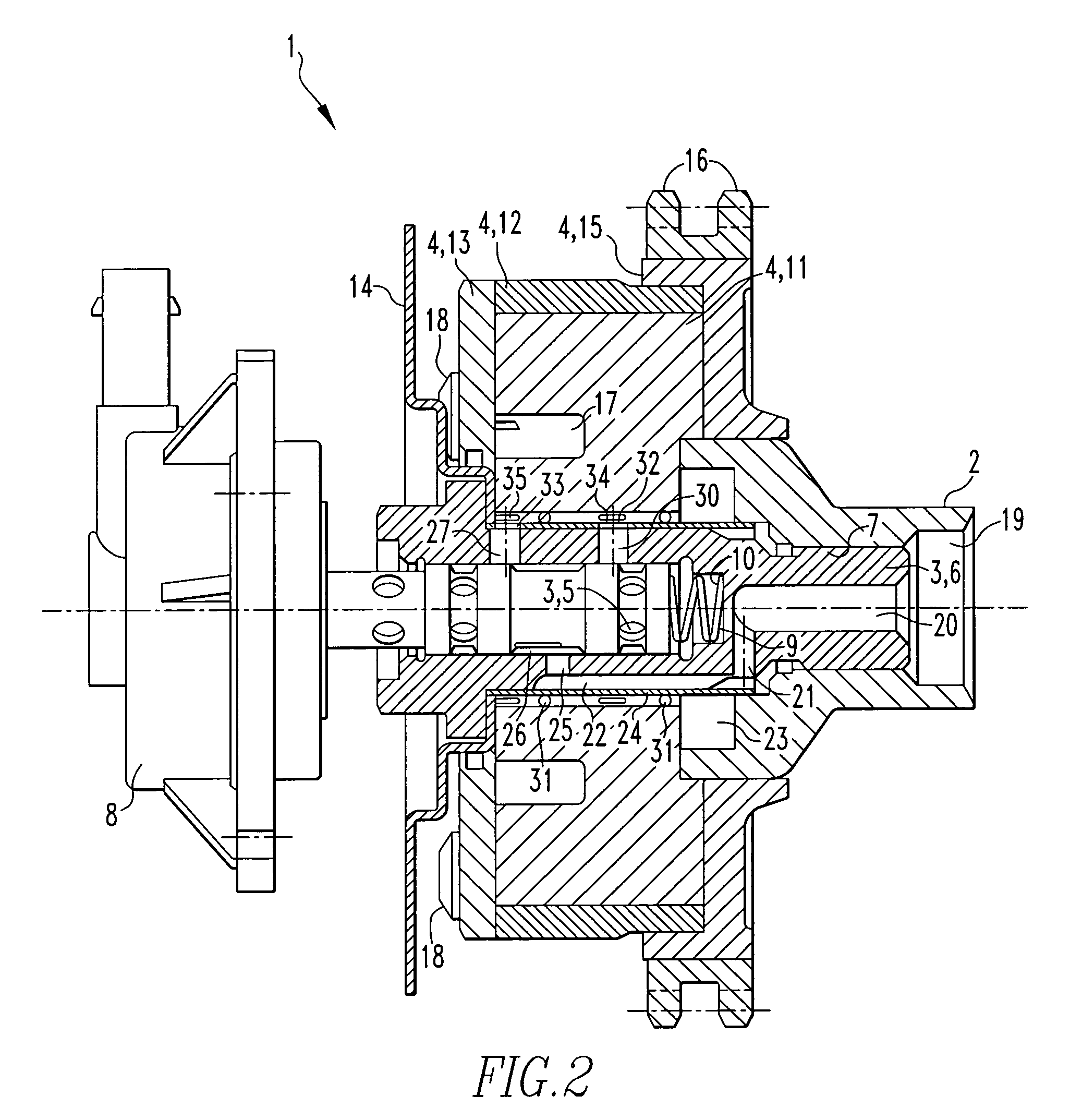
[0014]The camshaft adjuster as shown in FIGS. 1 and 2 is indicated generally by the numeral 1 and is shown mounted on a camshaft 2 of an internal combustion engine. The camshaft adjuster comprises a hydraulic control valve 3 and an operating unit 4 for adjusting the angular position of the camshaft 2 relative to a crankshaft of an engine.

[0015]The hydraulic control valve 3 includes a control piston 5 disposed in a valve housing 6. The valve housing 6 is firmly mounted in an axial opening 7 formed into one end of the camshaft 2 for example by welding or bolting.

[0016]At the end of the control piston 5 remote from the camshaft 2, an electromagnetic operating device 8 is mounted on the engine by way of which the control piston 5 is movable against the force of a compression spring 9 disposed in the valve housing supported on the bottom 10 of the valve housing adjacent the camshaft 2. The electromagnetic operating device 8 may be a pressure force generating magnet 8 or a pulling magnet,...


PUM


Abstract

In a hydraulic camshaft adjuster for an internal combustion engine including a hydraulic operating unit for adjusting the angular position of the camshaft relative to a camshaft drive by way of a hydraulic control valve with a valve housing in which a control piston is disposed for controlling the supply of hydraulic fluid to, and its removal from, the hydraulic operating unit and to which hydraulic fluid is supplied from the camshaft by way of a pressure channel which is formed into the valve housing so as to extend along the outer surface thereof and a sleeve tightly surrounds at least the part of the valve housing which includes the channel for tightly covering the channel.

Description

BACKGROUND OF THE INVENTION[0001]The invention relates to a hydraulic camshaft adjuster for an internal combustion engine with a camshaft including a control valve having a control piston axially movably disposed in a valve housing for controlling the admission of hydraulic fluid to, and the release thereof from, a device for adjusting the angular position of the camshaft relative to the crankshaft of the engine.[0002]For lowering the fuel consumption and the raw emissions of an engine and for increasing the engine power and engine torque gasoline engines are often provided with camshaft adjusters. The camshaft adjusters adjust the angular position of the camshaft relative to the crankshaft of the engine. Today, mostly hydraulic blade controllers with hydraulic operating chambers are used. The angular adjustment is performed by the controlled supply of oil from the engine oil circuit to the operating chambers of the blade controllers. The oil supply and the release of the oil is con...

Claims


Application Information

Patent Timeline
Patent Type & Authority Patents(United States)
IPC IPC(8): F01L1/34F01L1/18F01L1/344
CPCF01L1/022F01L1/3442F01L1/024Y10T74/2102F01L2001/3443F01L2001/34453F01L2820/041F01L2001/34426
Inventor LEHMANN, KAIPLANK, JENS-UWEROSENER, JORGRUDZINSKI, HOLGER
Owner DAIMLER AG
Why Eureka
Try Eureka