Extended depth of field optics for human vision

a technology of optics and depth of field, applied in the field of extended depth of field optics for human vision, can solve the problems of loss of contrast, out-of-focus image, image not aligned, etc., and achieve the effect of increasing the depth of field and prolonging the field

Inactive Publication Date: 2006-04-11
UNIV OF COLORADO THE REGENTS OF
View PDF113 Cites 60 Cited by
  • Summary
  • Abstract
  • Description
  • Claims
  • Application Information

AI Technical Summary

Benefits of technology

[0011]An object of the present invention is to provide extended depth of field (EDF) by modifying contact lenses, intraocular implants, and / or natural human eyes. This is accomplished by applying selected phase variations to these optical elements (e.g., by varying surface thickness of the cornea of the eye). These phase variations EDF encode the wavefront and cause the optical transfer function to remain essentially constant within a large range of distances from the in-focus position. The human brain undoes the EDF-coding effects, resulting in an in-focus image over an increased depth of field. While the human brain cannot compensate for general out-of-focus images, where the amount of blur changes with distance from the in-focus plane, it can compensate for the specific EDF-coding misfocus added by the optical mask, because that misfocus does not change with distance, and the phase variations are selected so that little or no information is lost in the process.

Problems solved by technology

The major disadvantage of this technique is that if the two images are not aligned (as occurs when the lens is not centered, a frequent occurrence with contact lenses) the images do not line up and the out-of-focus image is apparent.
Another disadvantage is loss of contrast.
The situation is even worse when the object is located between a reading distance and a very long distance; examples include the distance to a computer screen, a television set, or music on a stand.
This approach works for many people, but the inability to fuse images that are not both focused has made this solution unusable for many others because the user sees two misregistered images.
The human brain cannot adjust to conventional out-of-focus images, because the amount of blur changes with misfocus, or with distance from the in-focus plane.
In addition, the blur is such that some information about the object being seen is lost.

Method used


Image

  • Extended depth of field optics for human vision
  • Extended depth of field optics for human vision
  • Extended depth of field optics for human vision

Examples


Embodiment Construction

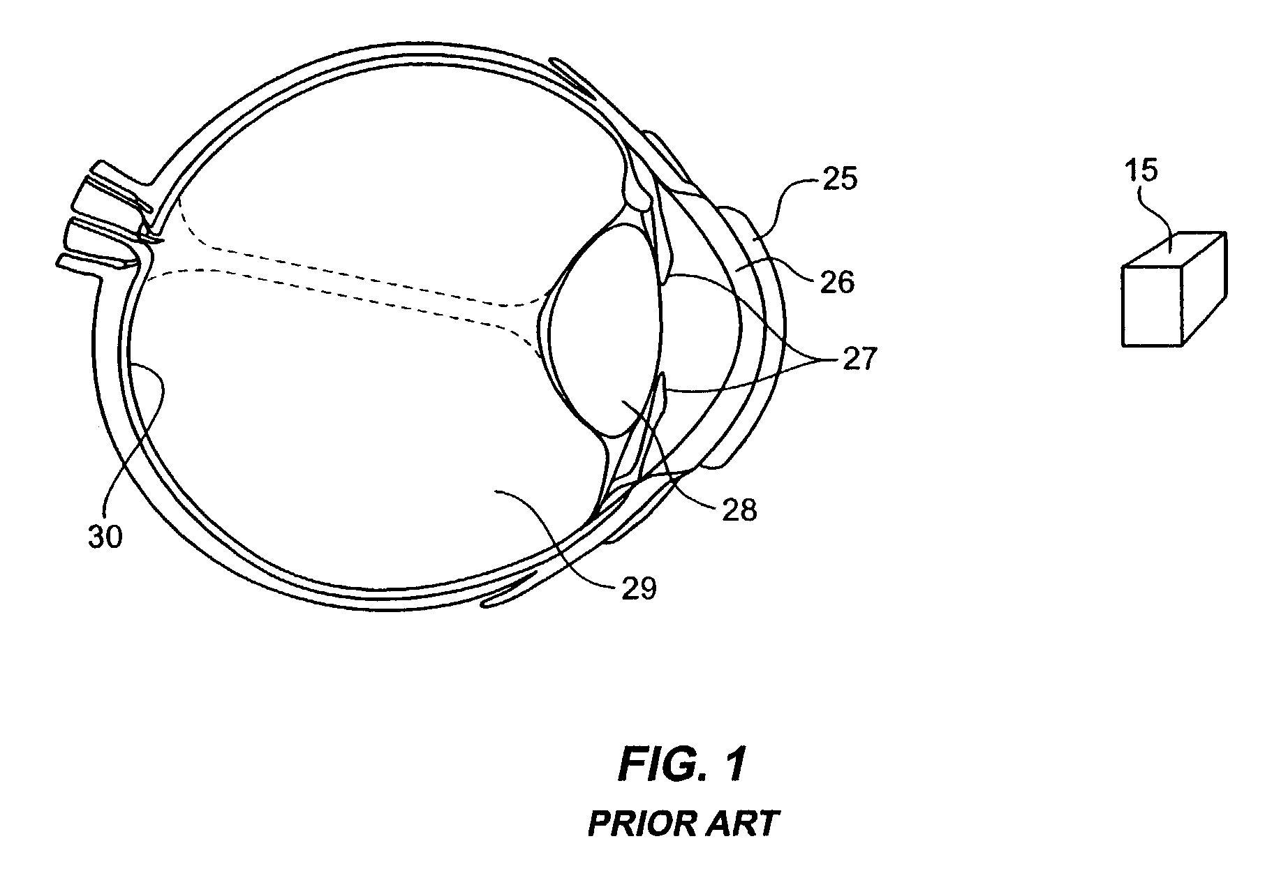
[0019]FIG. 1 (prior art) shows a conventional optical imaging system using a contact lens over an eye. Object 15 is imaged through contact lens 25 through the cornea 26, the iris 27, lens 28, and the vitreous humor 29 onto the retina 30. Such a system creates a sharp, in-focus image at the retina 30 only if object 15 is located at or very close to the in-focus object plane. Some accommodation is provided by the lens 28. However, lens 28 hardens with age and loses its ability to refocus. If the distance from the back principal plane of lens 28 to retina 30 is di, and the focal length of contact lens 25 is f, the distance from the front principal plane of lens 28 to object 15, do must be chosen such that:

[0020]1do+1di-1f=0(Eq.⁢1)

in order for the image at retina 30 to be in adequate focus. The depth of field of an optical system is the distance that the object 15 can move away from the in-focus distance and still have the image be in focus. For a simple system like FIG. 1, the depth of...


PUM


Abstract

The present invention provides extended depth of field to human eyes by modifying contact lenses, intraocular implants, and / or the surface of the eye itself. This may be accomplished by applying selected phase variations to these optical elements (e.g., by varying surface thickness of the cornea of the eye). The phase variations EDF-code the wavefront and cause the optical transfer function to remain essentially constant within a range of distances from the in-focus position. This provides a coded image on the retina. The human brain decodes this coded image, resulting in an in-focus image over an increased depth of field.

Description

CROSS-REFERENCE TO RELATED APPLICATIONS[0001]U.S. Pat. No. 5,748,371 (issued May 5, 1998) entitled “Extended Depth of Field Optical Systems” is incorporated herein by reference. This application is a continuation of commonly-owned and U.S. patent application Ser. No. 09 / 663,883 (filed Sep. 15, 2000) now U.S. Pat. No. 6,536,898, which is incorporated herein by reference.BACKGROUND[0002]This invention relates to apparatus and methods for increasing the depth of field and decreasing wavelength sensitivity of incoherent optical systems. In particular, this invention relates to extended depth of focus optics for human vision.DESCRIPTION OF THE PRIOR ART[0003]In the human eye, it is well known that the accommodation of the lens decreases with age, and that bifocal or trifocal glasses are eventually needed in many cases. When an eye lens must be replaced, an intraocular implant is usually designed for viewing objects at infinity, and the person then uses reading glasses and other glasses o...

Claims


Application Information

Patent Timeline
Patent Type & Authority Patents(United States)
IPC IPC(8): G02B7/02A61F2/14A61F2/16G02B3/00G02C7/04
CPCA61F2/16G02B3/00G02C7/042G02C7/04G02C7/028A61F2250/0036A61F2002/1699A61F2/1624G02C7/024
Inventor CATHEY, JR., WADE THOMAS
Owner UNIV OF COLORADO THE REGENTS OF
Why Eureka
Try Eureka