
Apparatus for surface conditioning

a surface conditioning and apparatus technology, applied in the direction of coatings, chemical vapor deposition coatings, metallic material coating processes, etc., can solve the problems of non-uniform gas distribution, safety, waste disposal, cleanliness and cost, and additional damage and contamination of the substrate surface of the substrate, so as to achieve better results

Inactive Publication Date: 2006-04-11
FSI INTERNATIONAL INC
View PDF67 Cites 56 Cited by
  • Summary
  • Abstract
  • Description
  • Claims
  • Application Information

AI Technical Summary

Benefits of technology

[0018]The purpose of the present invention is to provide an apparatus for conditioning of the surface of a substrate, in a preferably plasma-less gas phase environment, which overcomes the limitations of the prior art described above. The invention overcomes the limitations discussed above by creating a uniform peripherally directed gas flow which causes the gas, after it has reacted with the substrate surface, to flow radially outward to the substrate edge. The invention also overcomes the limitations discussed above by operating in a viscous flow regime. The present invention can be used to perform all of the plasma-less methods discussed above in connection with the prior art, and to obtain better results.

Problems solved by technology

The liquid aqueous chemical processes have problems involving safety, waste disposal, cleanliness and cost, and these problems make the use of gaseous processes very attractive.
These types of processes have the disadvantage of causing additional damage and contamination of the substrate surface.
Processes of the type disclosed in Hall or Ligenza have the disadvantages of non-uniform gas distribution and of a static gas regime which does not allow the transport of contaminants and etching residues out of the reactor during the etch reaction.
Applicants have found that systems of the type directing a flow of gas which chemically reacts, with or without photochemical activation, with the substrate as it flows across the surface provides undesirable non-uniform etching, cleaning or bulk stripping.
Applicants have also found that a device employing rotation of the substrate, in combination with the flow of gas across the substrate can cause a vortex or eddy effect which also can produce undesirable non-uniform effects.
All of the methods or devices discussed above have the disadvantage of either non-uniform gas distribution or non-uniform UV illumination, and the further disadvantage that none of the prior processes remove gas which has reacted with the substrate in a manner which minimizes the risk of further contamination.

Method used


Image

  • Apparatus for surface conditioning
  • Apparatus for surface conditioning
  • Apparatus for surface conditioning

Examples


Embodiment Construction

[0039]While this invention may be embodied in many different forms, there are shown in the drawings and described in detail herein specific preferred embodiments of the invention. The present disclosure exemplifies the principles of the invention. This disclosure is not intended to limit the invention to the particular embodiments illustrated.

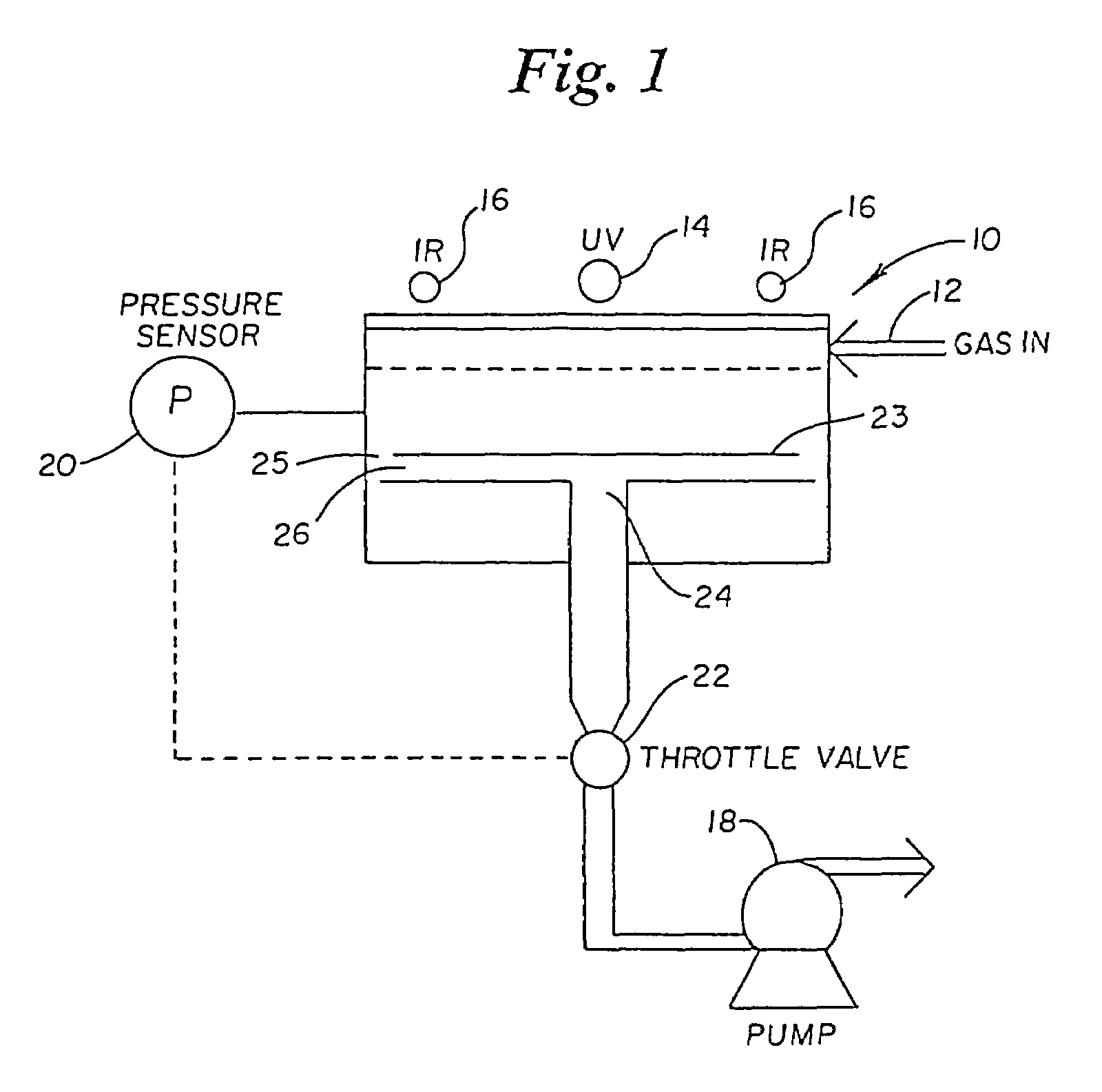
[0040]FIG. 1 is a schematic diagram of the major component parts of the system which make up the inventive apparatus. The inventive hermetically sealed chamber is shown generally at 10. The gas supply inlet is shown at 12 and is connected to the chamber 10, as discussed further below. An optional ultraviolet lamp is shown at 14, which is used to activate the conditioning gas, as is well known in the art. Optional infrared lamps are shown at 16 which can be used to heat the substrate, as is well known in the art. A vacuum pump 18 is connected to the chamber 10. A pressure sensor 20, positioned near the chamber wall and above the substrate, measu...


PUM

PropertyMeasurementUnit
diameteraaaaaaaaaa
diameteraaaaaaaaaa
diameteraaaaaaaaaa

Abstract

Apparatus and process for conditioning a generally planar substrate, contained in a chamber isolatable from the ambient environment and fed with a conditioning gas which includes reactive gas. The apparatus includes a support for supporting the substrate in the chamber, the substrate being in a lower pressure reaction region of the chamber. A gas inlet is provided for feeding conditioning gas into a gas inlet region of the chamber which is at a higher pressure than the lower pressure reaction region so that the pressure differential causes the conditioning gas to flow toward the surface of the substrate wherein the conditioning gas component will chemically react with and condition the substrate surface, both said higher and lower pressure regions operating in a viscous flow regime. The substrate is supported such that a pressure bias is created across the surface of this substrate so that the gas, after it has chemically reacted with the substrate surface, flows outward from where it has reacted, off the substrate toward the periphery of the chamber and out a peripheral or central underside exhaust outlet. Gas feed may be provided to one or both sides the substrate and light activation of the substrate or conditioning gas may be provided on one or both sides.

Description

[0001]This application is a continuation of application Ser. No. 08 / 860,071, filed Sep. 02, 1997 now U.S. Pat. No. 6,015,503, which is a Continuation of US national stage entry of PCT / US95 / 16649, filed 21 Dec. 1995.BACKGROUND OF THE INVENTION[0002]1. Field of the Invention[0003]The present invention relates to an apparatus which provides for the conditioning of the surface of a substrate in a plasma-less gas phase environment. It finds particular application in etching, cleaning, or bulk stripping removal of films or contaminants from the surface of a semiconductor wafer for use in the fabrication of integrated circuits.[0004]2. Description of the Related Art[0005]The traditional standard for surface contamination removal in the semiconductor industry is the RCA clean which uses liquid aqueous chemicals. Highly selective bulk film stripping is also commonly carried out with liquid aqueous chemicals. The liquid aqueous chemical processes have problems involving safety, waste disposal...

Claims


Application Information

Patent Timeline
Patent Type & Authority Patents(United States)
IPC IPC(8): C23C16/48C23F1/00H01L21/306
CPCC03C15/00C03C23/0075C23F1/00H01L21/67115C23G5/00H01L21/02046H01L21/31116C23F1/12
Inventor BUTTERBAUGH, JEFFERY W.GRAY, DAVID C.FAYFIELD, ROBERT T.SIEFERING, KEVINHEITZINGER, JOHNHIATT, FRED C.
Owner FSI INTERNATIONAL INC
Learn More