Multilayer composite armour

a composite armour and armor technology, applied in the field of multi-layer armor, can solve the problems of low performance with multiple impacts, lack of guaranteed protection effectiveness, and difficulty in fabricating, and achieve the effects of no weaknesses in integrity or strength, no weaknesses in integration flexibility, and easy fabrication

Inactive Publication Date: 2006-04-11
ARC LEICHTMETALLKOMPETENZ ZENT RANSHOFEN GMBH +1
View PDF7 Cites 23 Cited by
  • Summary
  • Abstract
  • Description
  • Claims
  • Application Information

AI Technical Summary

Benefits of technology

[0010]The goal of the invention is to remedy the aforesaid difficulties by providing a light, effective armor that is easy to fabricate, has unparalleled integration flexibility, and has no weaknesses in integrity or strength in the event of cracking of the composite layer.

Problems solved by technology

These types of armor, although their performance is satisfactory, are generally difficult to fabricate and do not have guaranteed protection effectiveness that is identical for all angles of attack, for all impact points on the front face, and also have low performance with multiple impacts (two successive shots striking the same impact zone).
Moreover, in view of the nature and shape of the reinforcement bodies used, and in view of the implementation difficulties, the cost of the protection thus obtained is generally high by comparison to armor composed of monolithic materials.
Finally, the exceptional compressive strength performance of ceramics is not fully exploited due to the confinement configurations recommended by the various inventors, which do not exhibit an optimal configuration.
The technique proposed by McDougal et al. has been criticized for its implementation difficulty and the risk inherent in the process of damaging the ceramic by thermal shock during the liquid metal coating phase.
However, such an armor cracks when struck by a projectile and when other plates made of metal, for example, are associated therewith by cementing or welding, separations occur between the plates which is detrimental to the integrity and strength of the whole or the welds break due to shear forces, leading once again to a reduction in the integrity and strength of the whole.

Method used


Image

  • Multilayer composite armour
  • Multilayer composite armour
  • Multilayer composite armour

Examples


Embodiment Construction

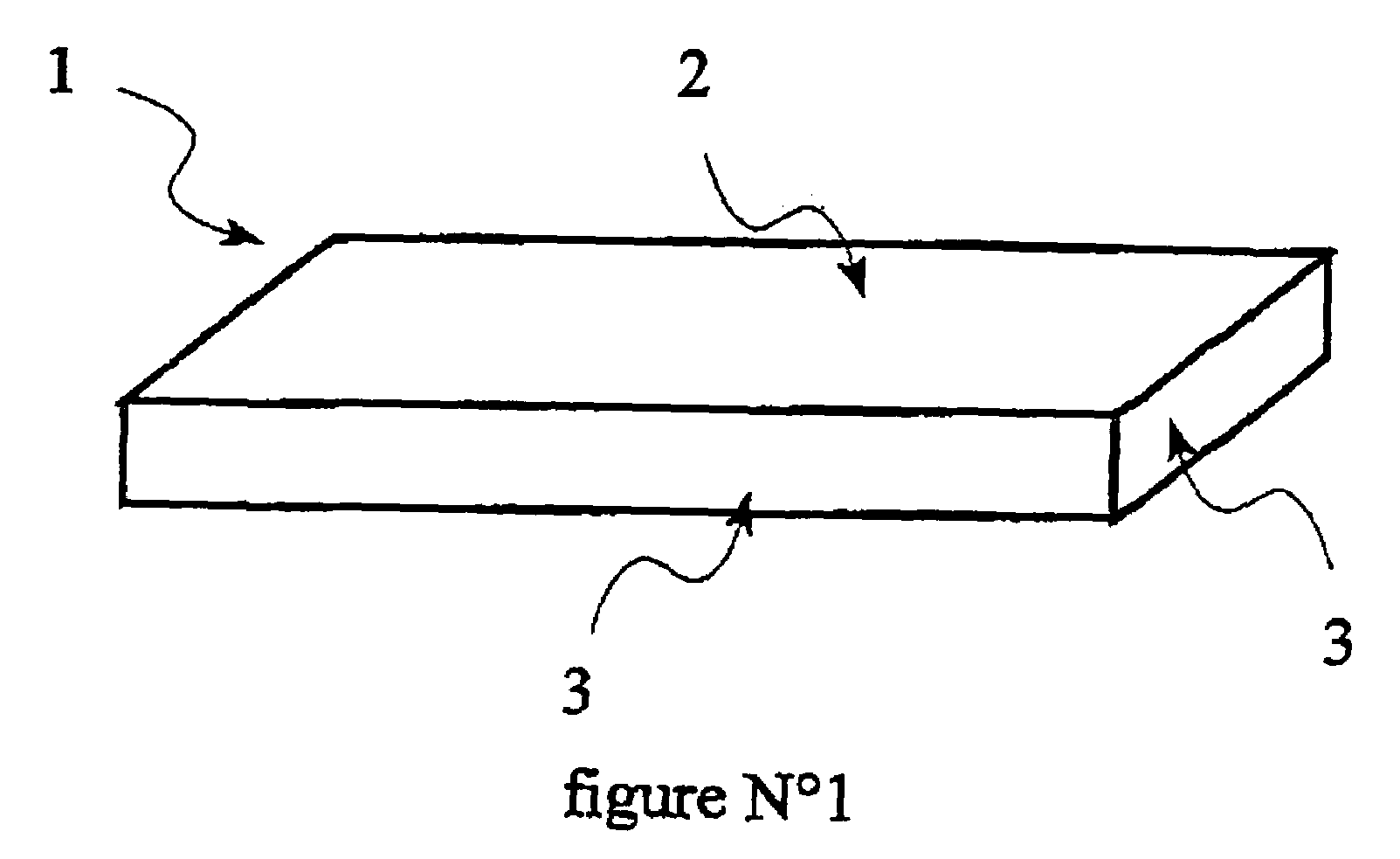
[0029]FIG. 1 is a perspective view of an example of a body 1 made of porous reinforcing material designed to enter into the composition of the armor. This body 1 is parallelepipedic in shape and is a ceramic. It is made of recrystallized silicon carbide. Its void ratio is 15%. This body has two large transverse surfaces 2 and small lateral surfaces 3.

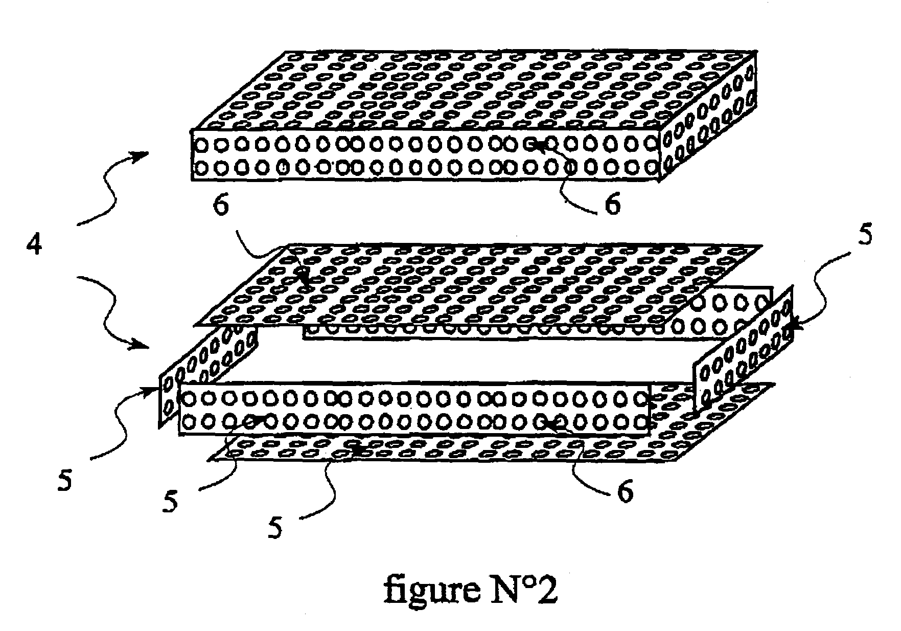
[0030]FIG. 2 is a perspective view of an example of a metal cage 4 designed to enclose said body 1 made of porous reinforcing material. This cage 4 is composed of steel plates 5 having regularly disposed circular openings 6. These plates 5 are welded together to form a cage 4 inside which the body 1 made of porous reinforcing material can be positioned, at least one of the faces of the parallelepiped being welded once the porous body 1 has been placed inside cage 4.

[0031]The dimensions of the cage 4 and the porous body 1 are such that there is several millimeters or even more of play between one of the transverse faces 2 of the porous b...


PUM

PropertyMeasurementUnit
void ratioaaaaaaaaaa
thickaaaaaaaaaa
impact velocitiesaaaaaaaaaa

Abstract

The invention relates to the area of armor and in particular to multilayer armor having a composite layer containing a first material made of a metal or an alloy and a second material where the second material is porous and in that the metal or metal alloy is infiltrated into some or all of the pores of the second material and characterized in that a cage made of plates having openings contains the first and second materials and in that the cage is itself coated, at least partly, with the infiltration metal or alloy, the melting point of the cage material being higher than that of the infiltration metal or alloy.

Description

BACKGROUND OF THE INVENTION[0001]The invention relates to the area of armor and in particular multilayer armor having a composite layer containing a first material, for example a ceramic, and a second material, such as a metal or metal alloy.[0002]Ceramic has been known for its ballistic performance for a number of years, either as a material placed at the front face of a piece of armor or embedded in the metal material to increase overall armor effectiveness.[0003]The most significant work in the area of cast composite armor has related mainly to production of armor with a series of ceramic reinforcements distributed in a metal matrix, generally obtained by a process related to casting.[0004]These types of armor, although their performance is satisfactory, are generally difficult to fabricate and do not have guaranteed protection effectiveness that is identical for all angles of attack, for all impact points on the front face, and also have low performance with multiple impacts (tw...

Claims


Application Information

Patent Timeline
Patent Type & Authority Patents(United States)
IPC IPC(8): B32B3/06F41H5/04
CPCF41H5/0421Y10S428/911Y10T428/249955Y10T428/249957Y10T428/24998
Inventor RETTENBACHER, GOTTFRIEDREITER, JOSEFFEUCHTENSCHLAGER, FRANZSCHULZ, PETERLOUVIGNE, PIERRE-FRANCOIS
Owner ARC LEICHTMETALLKOMPETENZ ZENT RANSHOFEN GMBH
Why Eureka
Try Eureka