Surface interaction region methodology for delimiting multipath propagation inquiry

Inactive Publication Date: 2006-04-11
THE UNITED STATES OF AMERICA AS REPRESENTED BY THE SECRETARY OF THE NAVY
View PDF14 Cites 12 Cited by
  • Summary
  • Abstract
  • Description
  • Claims
  • Application Information

AI Technical Summary

Benefits of technology

[0022]Fourthly, the present invention's DFS method accurately calculates the total multipath contribution without having to model both the scattering surface (e.g., terrain surface or sea surface) and the target simultaneously. Instead, only the forward scatter transfer function F1 needs to be calculated for the terrain/sea surface in question. This calculation can be done beforehand using any accurate forward scattering model. Once this transform and the bistatic scattering cross section are known, the actual multipath calculation becomes a fast and straightforward process. Furthermore, the forward scatter transform functions can be reused for other target geometries; thus, they only need to be calculated once for a specific terrain/sea surface and range-to-target.
[0023]In general, for most forward scattering and/or multipath scenarios, the ranges are many thousands of wavelengths, requiring very large regions of water (and/or land) to be modeled. The present invention's SIR method allows for modeling only the surface region that significantly contributes to the forward scattering, thereby reducing the modeled domain. This inventive “surface interaction region” (the region that significantly contributes to the forward scattering) is determined from experimental and numerical observations for given sea states and graz

Problems solved by technology

Sea clutter is a kind of environmental noise.
There are several problems with the traditional four-route multipath notion.
Currently there are no validated rigorous models for multipath.
Studies have shown that the experimental data matching cannot be easily extrapolated to terrain and sea surfaces other then those of the experiment; hence, this method is generally not applicable in the absence of a priori forward scattering know

Method used


Image

  • Surface interaction region methodology for delimiting multipath propagation inquiry
  • Surface interaction region methodology for delimiting multipath propagation inquiry
  • Surface interaction region methodology for delimiting multipath propagation inquiry

Examples


Embodiment Construction

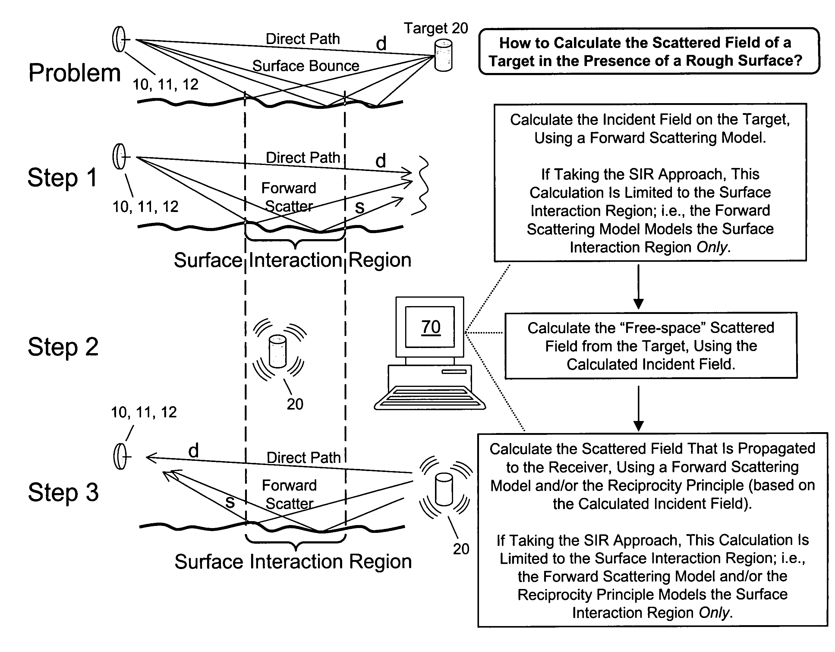
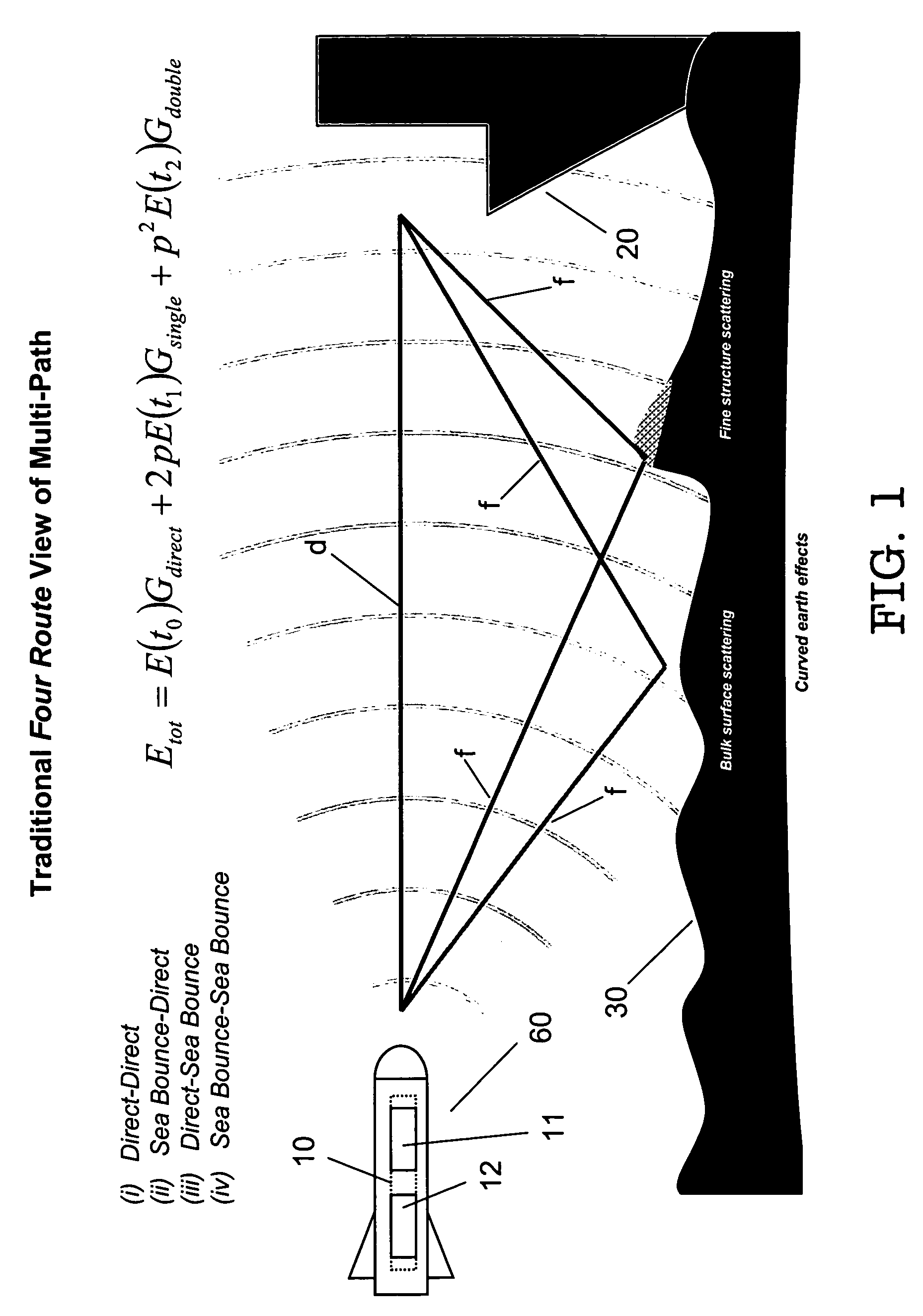
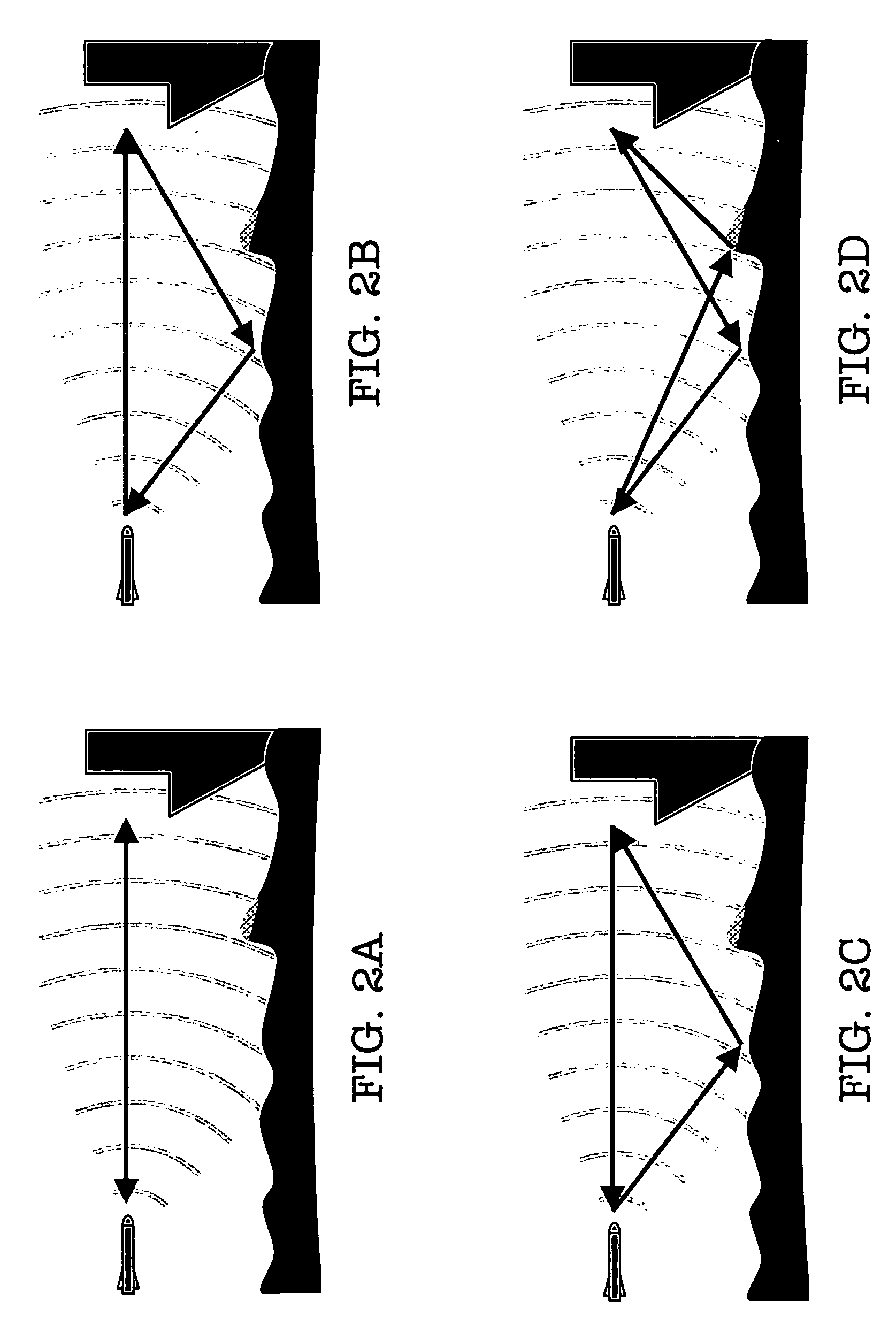
[0039]Referring now to FIG. 1 and to FIG. 2A through FIG. 2C, transmitter-receiver 10 includes transmitter 11 and receiver 12. The direct path d of radar from transmitter-receiver 10 (more specifically, transmitter 11) to target 20 represents the line of sight therebetween. A direct path calculation aims to find the free space portion of the incident field, i.e., that which the receiving target 20 would see in a free-space simulation. Forward scattering s from transmitter 11 to target 20 represents the deviation, in the incident field, relative to the direct path d field. A forward scattering s calculation aims to find the non-free space portion of the incident field. As depicted in FIG. 1 and FIG. 2A through FIG. 2C, transmitter-receiver 10 (which includes the combination of a transmitter 11 and a receiver 12) is the radar apparatus that is housed in a missile 60. Target 20 is a ship, and the scatter surface 30 is a sea surface (e.g., a “roughened” sea surface). In general, accordi...


PUM


Abstract

Analysis of electromagnetic (or acoustic) multipath propagation inventively confines the assessment of multipath propagation to a “surface interactive region” (“SIR”), intermediate the target and transmitter and/or the target and receiver. The down range time of the propagation, translatable to range distance, is related to error associated with such restriction. A SIR scope is selected commensurately with acceptable error. Jointly disclosed (practicable therewith or thereapart) is inventive focus upon the transmitter-to-target propagation (transmitted propagation reaching target via both direct pathway and forward scattered pathway) and the target-to-receiver propagation (re-transmitted propagation reaching receiver via both direct pathway and forward scattered pathway). Transmitter-to-target propagation is calculated using conventional multipath modeling technique. The target's overall scattered field is calculated using the calculated transmitter-to-target propagation in conjunction with qualitative electromagnetic/acoustic target information. Target-to-receiver propagation is calculated using conventional multipath modeling technique and/or the reciprocity principle as applied to the calculated transmitter-to-target propagation.

Description

CROSS-REFERENCE TO RELATED APPLICATIONS[0001]This application claims the benefit of U.S. provisional application No. 60 / 475,778, filed 5 Jun. 2003, hereby incorporated herein by reference, entitled “Method for Modeling Multipath Propagation,” sole inventor Jerry Rosson Smith, Jr.[0002]This application also claims the benefit of U.S. provisional application No. 60 / 475,787, filed 5 Jun. 2003, hereby incorporated herein by reference, entitled “Method for Modeling a Surface Interaction Region,” sole inventor Jerry Rosson Smith, Jr.[0003]This application is related to the U.S. nonprovisional application being filed concurrently herewith, hereby incorporated herein by reference, entitled “Surface Interaction Region Methodology for Delimiting Multipath Propagation Inquiry,” sole inventor Jerry Rosson Smith, Jr.STATEMENT OF GOVERNMENT INTEREST[0004]The invention described herein may be manufactured and used by or for the Government of the United States of America for governmental purposes w...

Claims


Application Information

Patent Timeline
IPC IPC(8): G01S7/292
CPCG01S7/02G01S7/527G01S7/292
Inventor SMITH, JR., JERRY ROSSON
Owner THE UNITED STATES OF AMERICA AS REPRESENTED BY THE SECRETARY OF THE NAVY
Why Eureka
Try Eureka