Sensor arrangement

a sensor and arrangement technology, applied in the field of sensor systems, can solve the problems of large investment in sensor technology and overall error, and achieve the effect of simple construction

Inactive Publication Date: 2006-04-18
E E ELEKTRONIK GES
View PDF22 Cites 14 Cited by
  • Summary
  • Abstract
  • Description
  • Claims
  • Application Information

AI Technical Summary

Benefits of technology

[0005]It is an object of the present invention, therefore, to provide a sensor system that is simple to construct a

Problems solved by technology

Moreover, the control concept requires at least one further sensor for measuring the temperature, so that considerable outlay is entailed for sensor technology.
The drawback of this varian

Method used


Image

  • Sensor arrangement
  • Sensor arrangement
  • Sensor arrangement

Examples


Embodiment Construction

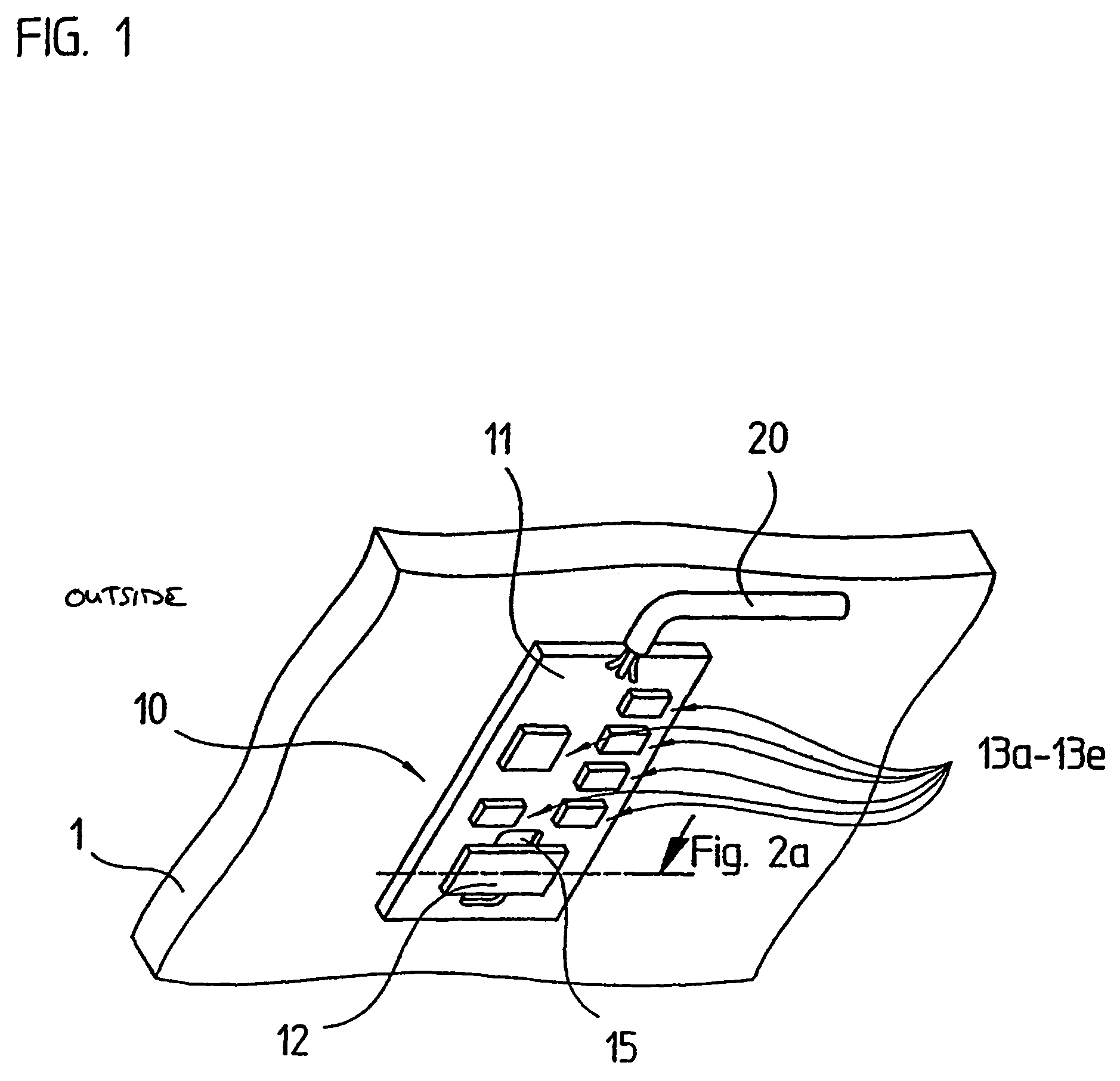
[0016]FIG. 1 illustrates a part of the inside of a motor vehicle windshield 1, which, in this exemplary embodiment, is used as a supporting surface and in which fogging is to be prevented. Sensor system 10 is mounted on the side of motor-vehicle windshield 1 facing the passenger compartment. FIG. 1 also illustrates a first example embodiment of such a sensor system. The output signals from sensor system 10 are fed via a connecting cable 20 to a controlled motor-vehicle air-conditioning system. On the basis of the delivered humidity-dependent sensor signals, the air-conditioning system prevents the inside of motor-vehicle windshield 1 from fogging and, thus, a potential sight obscuration. For this reason, it is possible to vary the heating temperature and / or the ventilation flow rate in a defined manner, via the motor-vehicle air-conditioning system.

[0017]Using sensor system 10 according to the present invention, it is merely the relative air humidity that is determined on that side ...


PUM

PropertyMeasurementUnit
Temperatureaaaaaaaaaa
Lengthaaaaaaaaaa

Abstract

A sensor arrangement is suitable for detecting if a windscreen of a motor vehicle is fogging. The sensor arrangement includes a heat conducting layer disposed on a supporting surface, the layer exhibiting good heat conducting properties. A support plate is arranged on top of the heat conducting layer, including a recess and several electrical conductor tracks. A moisture-sensitive sensor element is arranged in the region of the recess of the support plate. The sensor element is electroconductively connected to the conductor tracks on the support plate. The temperature difference between the sensor element and the supporting plate may not exceed a given limit when measurement occurs.

Description

FIELD OF THE INVENTION[0001]The present invention is directed to a sensor system which is suited, in particular, for detecting the fogging or misting of the inside of a motor-vehicle windshield.BACKGROUND INFORMATION[0002]Numerous approaches are conventional for avoiding the fogging of windshields in automobiles. U.S. Pat. No. 4,408,660, for instance, describes regulating the motor-vehicle air-conditioning system on the basis of output signals from many different types of sensors, in order to prevent fogging. Among the sensors used or required is a humidity sensor, which measures the relative humidity or the dew point on the particular motor-vehicle windshield. However, the foregoing does not include any further references to the specific arrangement of the humidity sensor. Moreover, the control concept requires at least one further sensor for measuring the temperature, so that considerable outlay is entailed for sensor technology.[0003]Another approach for dealing with the above pr...

Claims


Application Information

Patent Timeline
IPC IPC(8): G01N19/10B32B17/10G01N27/22B60H1/00B60S1/08B60S1/54
CPCB32B17/10018B32B17/1055B60H1/00785B60S1/0888B60S1/0825B60S1/0822B60S1/0881G01K1/16
Inventor NIKOLAUS, GERHARD
Owner E E ELEKTRONIK GES
Why Eureka
Try Eureka