
Pressurized plastic bottle for dispensing an aerosol

a technology of aerosol and plastic bottles, which is applied in the field of dispensers, can solve the problems of not sliding vertically and maintaining the desired spacing, and achieve the effect of minimizing any deformation

Inactive Publication Date: 2006-04-18
SC JOHNSON & SON INC
View PDF27 Cites 171 Cited by
  • Summary
  • Abstract
  • Description
  • Claims
  • Application Information

AI Technical Summary

Benefits of technology

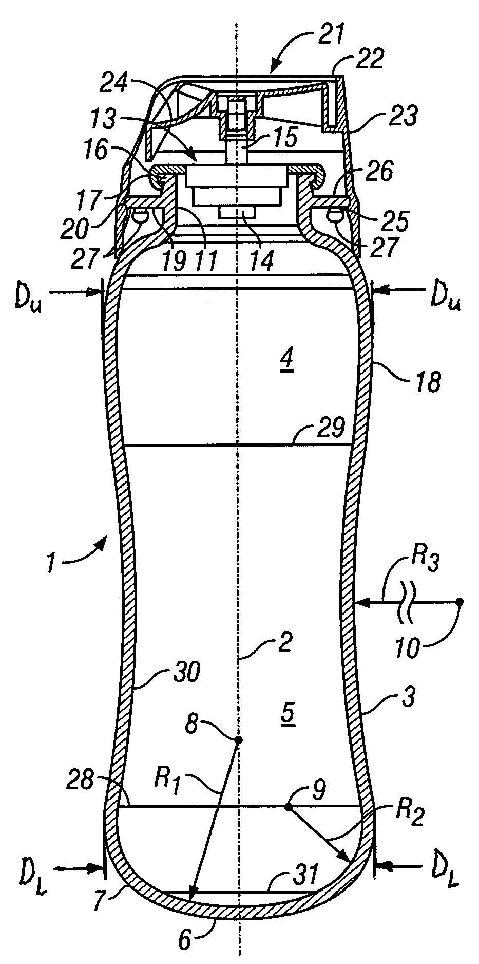
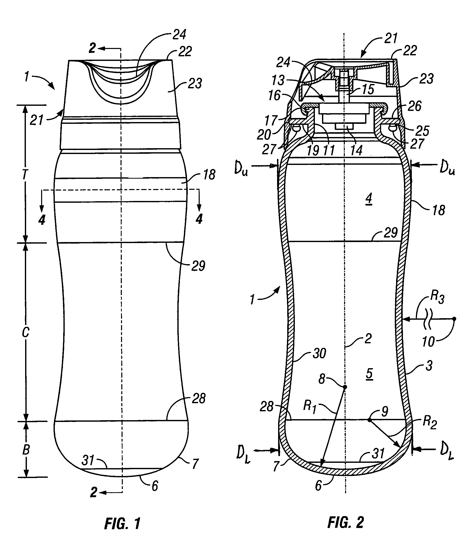
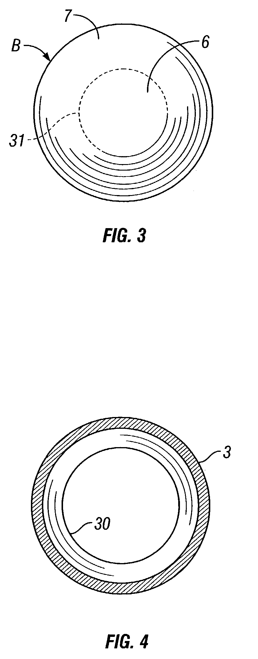
[0005]The present invention is directed toward a pressure resistant plastic bottle for containing and dispensing an aerosol composition. The plastic bottle is comprised of a hollow elongate body having a longitudinal axis and an outer wall. The outer wall defines a central portion, a top portion and an opposite bottom portion with the central portion having a circular cross-sectional configuration taken through a plane perpendicular to the longitudinal axis and having an inwardly projecting concave configuration extending along its longitudinal direction. Preferably, the central portion of the bottle has a hyperboloid configuration. The bottom portion of the elongate body is integral with the central portion and defines an outwardly projecting convexly shaped configuration extending along a direction transverse to said longitudinal axis. Preferably, the convexly shaped configuration comprises a base portion having a spherical end configuration and a side portion having a spherical segment configuration. This design of the central portion and bottom portion of the plastic bottle effectively resists the internal pressures generated by an aerosol to minimize any deformation. Further, any deformation that may occur results in a substantially uniform change which can be accommodated by the top portion of the plastic bottle.

Problems solved by technology

In contrast, bottles having straight surfaces where they touch, i.e. line contact, tend not to slide vertically and maintain a desired spacing during manufacture and filling.

Method used


Image

  • Pressurized plastic bottle for dispensing an aerosol
  • Pressurized plastic bottle for dispensing an aerosol
  • Pressurized plastic bottle for dispensing an aerosol

Examples


Embodiment Construction

[0014]Referring now to the drawings, there is illustrated a pressure resistant plastic bottle generally designated by the numeral 1 for containing and dispensing an aerosol composition. The plastic bottle 1 may be composed of any thermoplastic material that may be formed into the desired shape disclosed herein. Examples of such materials include ethylene based polymers, including ethylene / vinyl acetate, ethylene acrylate, ethylene methacrylate, ethylene methyl acrylate, ethylene methyl methacrylate, ethylene vinyl acetate carbon monoxide, and ethylene N-butyl acrylate carbon monoxide, polybutene-1, high and low density polyethylene, polyethylene blends and chemically modified polyethylene, copolymers of ethylene and C1–C6 mono- or di-unsaturated monomers, polyamides, polybutadiene rubber, polyesters such as polyethylene terephthalate, polyethylene naphthalate, polybutylene terephthalate; thermoplastic polycarbonates, atactic polyalphaolefms, including atactic polypropylene, polyviny...


PUM


Abstract

A pressure resistant plastic bottle for containing and dispensing an aerosol composition. The plastic bottle is comprised of a hollow elongate body having a central portion, a top portion and an opposite bottom portion with the central portion having an inwardly concave configuration extending along its longitudinal direction. The bottom portion of the elongate body is integral with the central portion and defines an outwardly projecting convexly shaped configuration. The top portion of the bottle is integral with the central portion and has an outwardly convex configuration extending along its longitudinal direction and defines a neck having an opening for receiving and dispensing the aerosol composition. A closure covers the opening and is sealingly attached to the neck to contain the aerosol within the plastic bottle.

Description

BACKGROUND OF THE INVENTION[0001]The present invention relates to dispensers for aerosols or other pressurized products, and more particularly to a pressure resistant plastic bottle for dispensing an aerosol or other comparably pressurized product.[0002]The term “aerosol” will be understood herein to encompass both aerosols, literally, and other liquid or flowable products that can be dispensed from pressurized containers in a manner comparable to aerosolized products. Such products include but are not limited to foamed or gel preparations or to liquid products delivered in a non-aerosol stream.[0003]Pressurized containers for dispensing aerosols are well known in the art, and are typically constructed of metal in order to withstand the inherent internal pressure of aerosols. However, it is desirable to provide a plastic container capable of withstanding the internal pressures generated by an aerosol because plastic has many advantages over metal. Some of these advantages include th...

Claims


Application Information

Patent Timeline
Patent Type & Authority Patents(United States)
IPC IPC(8): B65D83/00B65D83/14
CPCB65D83/38
Inventor KUNESH, EDWARD J.MILLER, ALLEN D.MATHER, DAVID P.SKALITZKY, MICHAEL J.BODA, JAMES C.BIRKHOLZ, DOUGLAS J.
Owner SC JOHNSON & SON INC
Learn More