Liquid-crystal display device

a display device and liquid crystal technology, applied in non-linear optics, instruments, optics, etc., can solve the problems of reducing the thickness and weight of the device as a whole, remarkably reducing the incidence of light on the side surface of the panel, and achieving excellent brightness

Inactive Publication Date: 2006-04-18
NITTO DENKO CORP
View PDF32 Cites 35 Cited by
  • Summary
  • Abstract
  • Description
  • Claims
  • Application Information

AI Technical Summary

Benefits of technology

[0008]An object of the invention is to develop a semi-transmission reflection layer-including liquid-crystal display device which can be used both in an external light mode and in an illumination mode and in which reduction in thickness and weight regarded as being hardly achieved by a side light type light pipe can be put into practice while the device is excellent in display luminance and its uniformity and good in display quality.
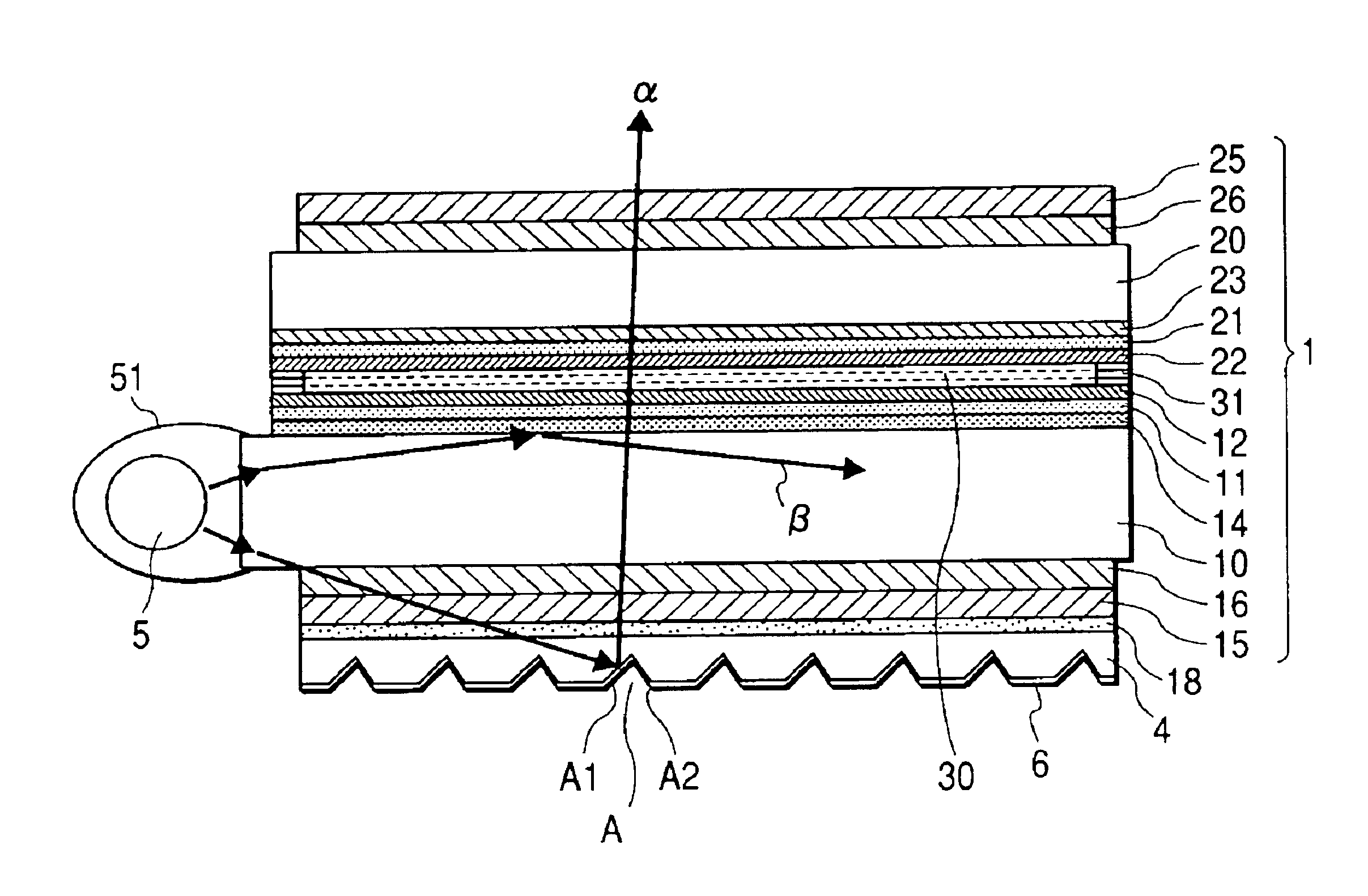
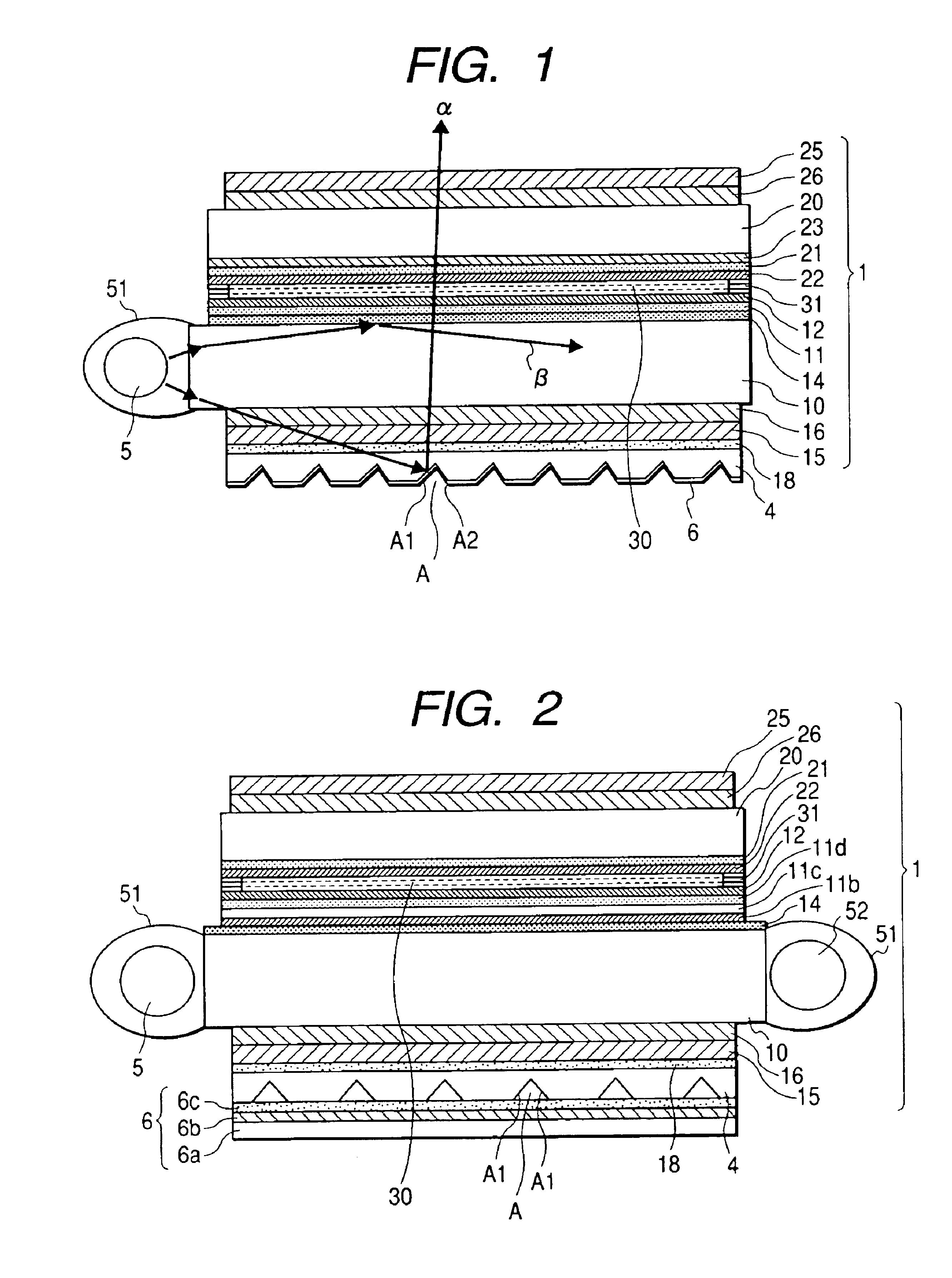
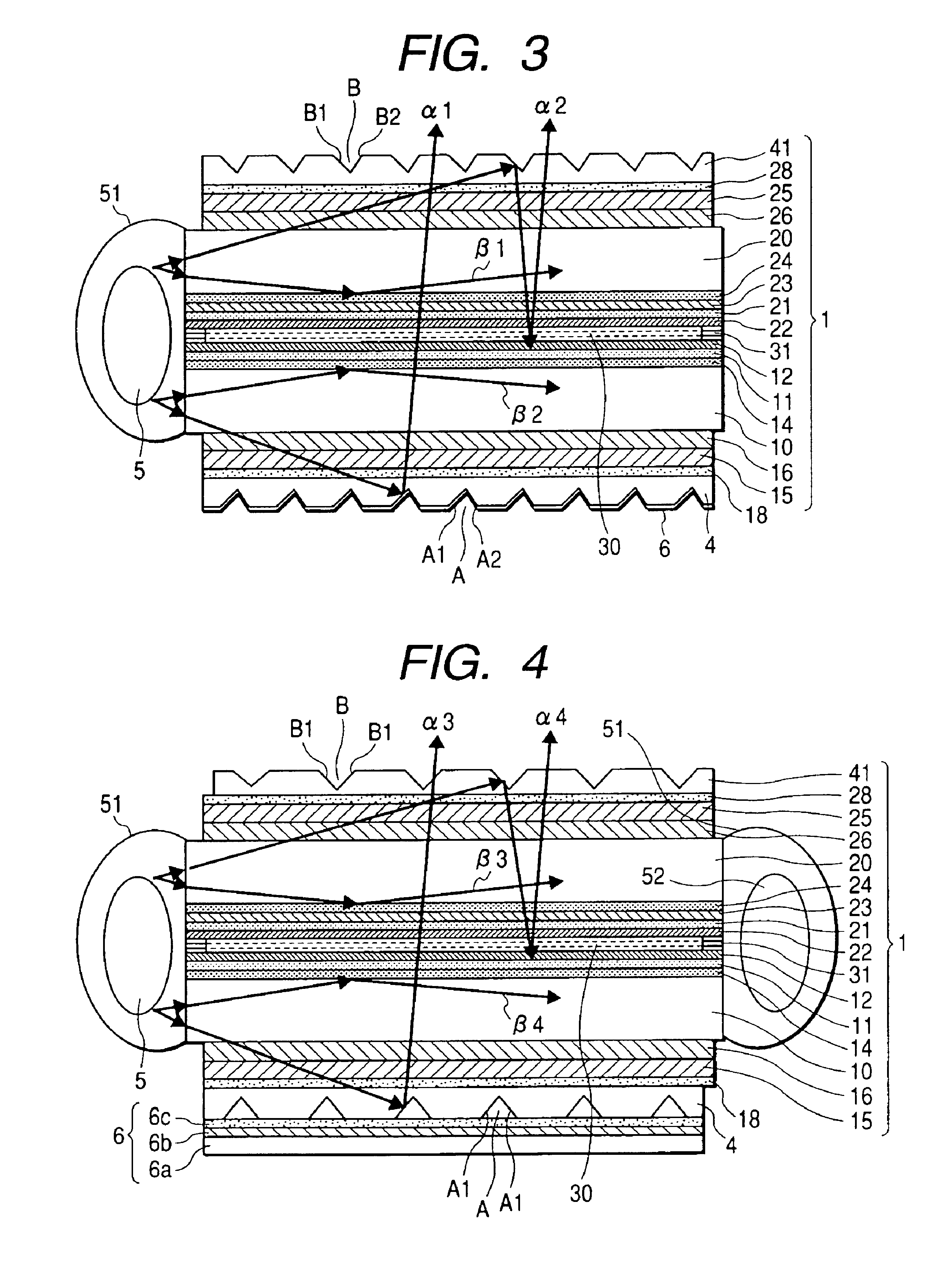
[0011]According to the invention, a backlight mechanism can be formed by the light source disposed on side surfaces and the optical path control layer excellent in thinness. While incident light from the light source(s) disposed on the side surface of the panel is transmitted toward the opposite side surface (s) efficiently through the insides of the visual side and back side substrates or the inside of one of visual side and back side substrates, the optical path of the transmitted light is changed efficiently to the visual side of the liquid-crystal display panel by the optical path control layer(s) disposed on the back side or on the visual side and on the back side respectively. Hence, the transmitted light can be utilized for liquid-crystal display in an illumination mode. Liquid-crystal display in an external light mode can be also achieved by the semi-transmission reflection layer. In this manner, there can be obtained a liquid-crystal display device which can be used both in an external light mode and in an illumination mode and which is excellent in reduction in thickness and weight, excellent in brightness and its uniformity and excellent in display quality.
[0012]The display device is obtained by use of the low-refractive-index transparent layer(s) provided in the only back side or both of visual side and back side cell substrates respectively, the slope-reflection type optical path control layer(s) and the semi-transmission reflection layer. That is, light incident on side surfaces or one side of the panel can be transmitted toward the opposite side surface(s) efficiently by the confinement effect due to total reflection based on the low-refractive-index transparent layers. Hence, uniformity of brightness in a display screen as a whole is improved, so that good display quality can be achieved. If there is no low-refractive-index transparent layer, display is not easy to view because backward transmission efficiency is so low that the display screen becomes darker as the position on the display screen becomes farther from the light source(s).
[0014]On the other hand, use of the semi-transmission reflection layer permits balance between its transmittance and its reflectance to be kept to thereby achieve liquid-crystal display excellent in brightness both in an illumination mode and in an external light mode.

Problems solved by technology

There is, however, the actual situation that reduction in thickness and weight of the device as a whole has reached its practical limit because even in the case where a related-art side light type light pipe excellent in thinness is used in a backlight unit to obtain good visibility in an illumination mode, the thickness of the backlight unit is generally not smaller than 2 mm.
There is, however, a problem that display luminance is low because the efficiency of incidence of light on a side surface of the panel is lowered remarkably with the reduction in thickness of cell substrates carried out in the recent years.
There is also a problem that it is difficult to make the distribution of luminance uniform when the transmission distance of light in the direction of the side surface is long compared with the thickness of the cell substrates, that is, when the area of the cell substrates is relatively large.
These problems arise also in the liquid-crystal display device which includes a semi-transmission reflection layer and which can be used both in an external light mode and in an illumination mode.

Method used


Image

  • Liquid-crystal display device
  • Liquid-crystal display device
  • Liquid-crystal display device

Examples


reference example 1

[0131]Magnesium fluoride vapor was vacuum-deposited on a non-alkali glass plate having a thickness of 0.7 mm and a refractive index of 1.52 to thereby form a low-refractive-index transparent layer having a thickness of 600 nm and a refractive index of 1.38. A resin layer of a surface fine roughness structure was provided on the low-refractive-index transparent layer. Then, aluminum vapor was vacuum-deposited on the resin layer, and 250 μm-square openings were formed by an etching method so as to be distributed evenly with a numerical aperture of 20%. Thus, a half-transmission reflecting layer was provided to serve also as an electrode. The half-transmission reflecting layer was spin-coated with a polyvinyl alcohol solution and the dried film of the polyvinyl alcohol solution was subjected to a rubbing treatment to thereby obtain a back side substrate. On the other hand, an ITO transparent electrically conductive layer was formed on a non-alkali glass plate provided in the same manne...

reference example 2

[0133]A normally white liquid-crystal panel having cold-cathode tubes held on opposite side surfaces was obtained in the same manner as in Reference Example 1 except that the low-refractive-index transparent layer of magnesium fluoride was not provided on the back side substrate.

reference example 3

[0134]An acrylic-based ultraviolet-curable resin (ARONIX UV-3701 made by TOAGOSEI CO., LTD.) was dropped by a dropper into a mold processed into a predetermined shape in advance so that the mold was filled with the acrylic-based ultraviolet-curable resin. A 60 μm-thick polycarbonate (PC) film was quietly placed on the acrylic-based ultraviolet-curable resin and then stuck closely thereto by a rubber roller so that a surplus of the resin and air bubbles were removed. Then, the acrylic-based ultraviolet-curable resin was irradiated with ultraviolet rays by a metal halide lamp so that the resin was cured. Then, the resin with the PC film was released from the mold and cut into a predetermined size. The PC film was released from the resin. Thus, an optical path control layer (transparent sheet) having a refractive index of 1.51 was obtained. An acrylic-based pressure sensitive adhesive layer having a refractive index of 1.51 was attached to a surface of the transparent sheet where the o...


PUM

PropertyMeasurementUnit
inclination angleaaaaaaaaaa
refractive indexaaaaaaaaaa
thicknessaaaaaaaaaa

Abstract

In a liquid-crystal display device, an optical path control layer is provided at least on an outer side of the back side substrate, and has a plurality of optical path changing slopes inclined at an inclination angle of from 35 to 48 degrees with respect to a reference plane of the back side substrate. The optical path control layer has a refractive index higher than that of a low-refractive-index transparent layer provided in the back side substrate. Another low-refractive-index transparent layer lower in refractive index than the transparent substrate may be provided in a visual side substrate. Light sources may be disposed on at least two side surfaces of the liquid-crystal display panel. Light sources may be disposed on side surfaces of the back side substrate and the visual side substrate and at least on side surfaces of the liquid-crystal display panel which are different from each other. Another optical path control layer may be provided also on an outer side of the visual side substrate.

Description

[0001]The present application is based on Japanese Patent Applications Nos. 2001-251282, 2001-251283 and 2001-251284, which are incorporated herein by reference.BACKGROUND OF THE INVENTION[0002]1. Field of the Invention[0003]The present invention relates to a liquid-crystal display device which is easy to reduce thickness and weight and excellent in display quality and which can be used both in an external light mode and in an illumination mode.[0004]2. Description of the Related Art[0005]A liquid-crystal display device which includes a semi-transmission reflection layer such as a half mirror and which can be used both in an external light mode and in an illumination mode has become popular widely in a portable apparatus such as a portable personal computer or a cellular phone. Reduction in weight achieved by reduction in size and thickness of the portable apparatus has been strongly demanded in order to improve its portability more greatly. There is, however, the actual situation t...

Claims


Application Information

Patent Timeline
Patent Type & Authority Patents(United States)
IPC IPC(8): G02F1/13G02F1/13357
CPCG02F1/133615
Inventor UMEMOTO, SEIJIKINOSHITA, RYOJINAKANO, YUUKIAMINO, ICHIROARIYOSHI, TOSHIHIKO
Owner NITTO DENKO CORP
Why Eureka
Try Eureka