Micro-oscillating element provided with torsion bar

a micro-oscillating element and torsion bar technology, which is applied in the direction of snap-action arrangements, generators/motors, instruments, etc., can solve the problems of high possibility, inability to meet various kinds of property requirements required of micro-mirror units, and the destruction of torsion bars 412 at the spot, etc., to achieve low possibility of destruction, large twisting angle, and low twisting resistance

Inactive Publication Date: 2006-04-18
FUJITSU LTD
View PDF14 Cites 28 Cited by
  • Summary
  • Abstract
  • Description
  • Claims
  • Application Information

AI Technical Summary

Benefits of technology

[0014]The objective of the present invention is to provide a micro-oscillating element, especially a micro-mirror unit, which has a low possibility of destruction even if the torsion bar is constructed to meet various kinds of requirements, such as low twisting resistance, a large twisting angle, and high resonance frequency.
[0016]According to the above construction, the rigidity of the torsion bar can be adjusted by the rigidity adjustment means according to the operation properties required of the micro-oscillating element. For example, it is possible to increase the rigidity of one end or both ends of the torsion bar and to increase the twisting spring constant. Conversely, it is also possible to decrease the rigidity of one end or both ends of the torsion bar and to set the twisting resistance to be small and the twisting angle large. Also, if the rigidity distribution is adjusted so that the stress distribution of a torsion bar deformed by twisting becomes uniform in the lengthwise direction, the possibility of torsion bar destruction due to the concentration of stress can also be reduced.
[0017]According to the preferred embodiment of the present invention, each connector contains two torsion bars having an interval in the widthwise direction, constructed so that the interval between the two torsion bars increases toward the oscillating member and decreases as they approach the frame. If thus constructed, when the oscillating member rocks, while each torsion bar mainly develops twisting deformation on the frame side, because the oscillating member side is far from the oscillating axis center, the degree of twisting deformation is small, and thus bending deformation becomes the main deformation. Therefore, the end of each torsion bar is in a state where it is difficult for stress concentration to occur.
[0019]The first means to adjust the rigidity of the torsion bar is to form a plurality of holes on the torsion bar to give variation to their size and arrangement pattern. The holes have the effect of reducing the rigidity of the torsion bar, and the greater the occupying ratio of the holes are, the stronger the effect becomes. Therefore, if the hole size varies so that it becomes smaller toward the frame and larger toward the oscillating member, the rigidity of the torsion bar becomes higher toward the frame and lower toward the oscillating member. On the other hand, if the size of the plurality of holes is made uniform, the same function can be obtained by varying the hole density to be smaller toward the frame and larger to ward the oscillating member.
[0023]According to an embodiment where each connection unit contains two torsion bars, when the oscillating member attempts to rotate around an axis (the so-called z axis) which is perpendicular to a plane containing the two torsion bars, the torsion bars perform a thrusting action to prevent the rotation of the oscillating member around the z axis. Therefore, if the oscillating member is the mirror section of a micro-mirror unit, it can prevent the mirror section from reflecting light in an unintended direction.
[0026]According to this embodiment, a dual axis oscillating type micro-oscillating element can be constructed, and if the oscillating member has a mirror section, the degree of freedom in the light reflection direction increases.

Problems solved by technology

As a result, when stress concentrates at both ends of each torsion bar 412, there is a high possibility that the torsion bar 412 will be destroyed at that spot.
Also, if the rigidity of the torsion bar 412 is uniform in the lengthwise direction, it is impossible to the meet various kinds of property requirements required of the micro-mirror unit 400.

Method used


Image

  • Micro-oscillating element provided with torsion bar
  • Micro-oscillating element provided with torsion bar
  • Micro-oscillating element provided with torsion bar

Examples


first embodiment

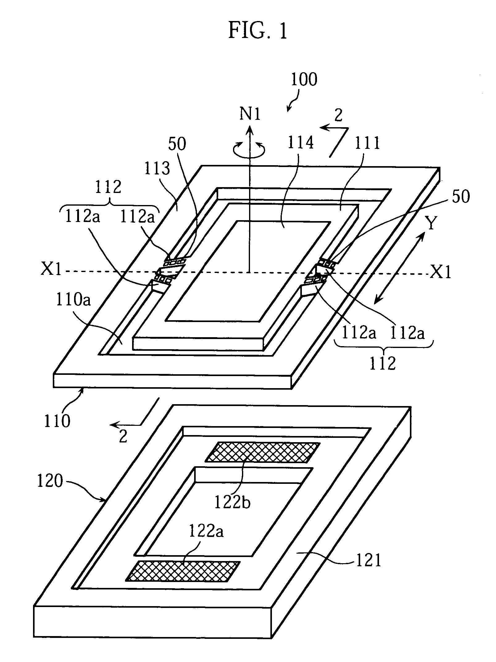
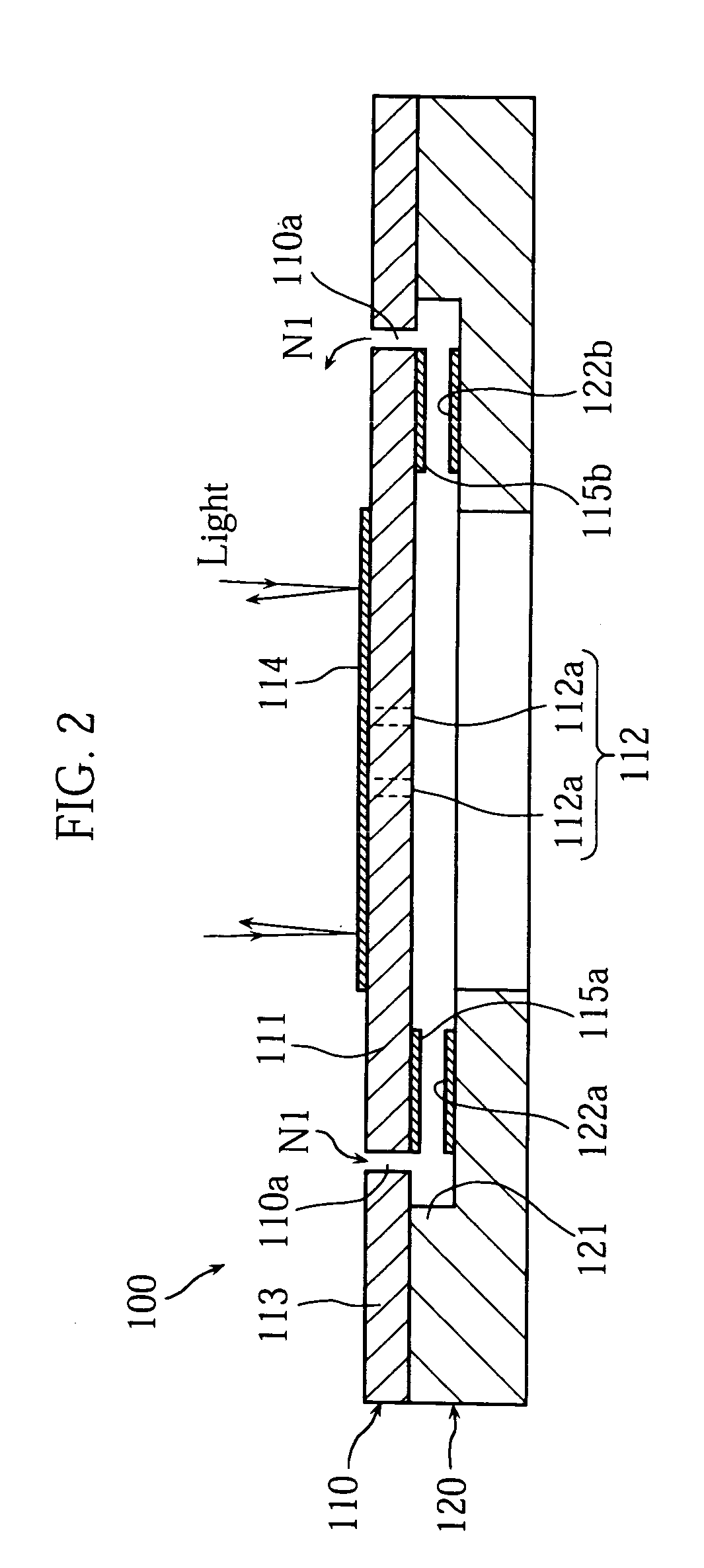
[0065]Preferred embodiments of the present invention are explained hereafter, with reference to the drawings. Shown in FIGS. 1 and 2 is a micro-mirror unit 100 related to the present invention. The micro-mirror unit 100 of the present invention has construction where a mirror substrate 100 and a base substrate 120 are accumulated.

[0066]As shown in FIG. 1, the mirror substrate 110 has a mirror section 111, a frame 113 which surrounds this mirror section 111, and a pair of twisting connector 112 which connect the fame 113 and a mirror section 111. The mirror substrate 110 is, for example, formed by bulk machining technology from a substrate made of silicon given conductivity by doping n-type impurities such as P and As and p-type impurities such as B. Specifically, an air gap section 110a is installed by performing dry etching such as Deep RIE (Deep Reactive Ion Etching) or wet etching with KOH solution etc. to a plate-shape conductive silicon substrate using an etching mask covering ...

second embodiment

[0078]Shown in FIGS. 3˜5 is a micro-mirror unit 200 related to the present invention. The micro-mirror unit 200 in the present embodiment has construction where a mirror substrate 210 and a base substrate 220 are accumulated via an insulation layer 230.

[0079]The mirror substrate 110 has, as shown in FIG. 3, a mirror section 211, a frame 213 which surrounds the mirror section 211, and a pair of twisting connectors 212 which connect the frame 213 and mirror section 211. The mirror substrate 210 is, for example, formed by means of bulk machining technology from a substrate made of silicon, and given conductivity by doping n-type impurities such as P and As and p-type impurity such as B. Specifically, an air gap section 210a is installed by performing dry etching such as Deep RIE or wet etching with a KOH solution etc. to a plate-shape conductive silicon substrate using an etching mask covering the mirror section 211, the frame 213, and the pair of twisting connectors 212. As a result, ...


PUM


Abstract

A micro-oscillating element is provided with a frame (113) and a oscillating member (111) connected with the frame (113) via a connector (112). Each connector (112) includes two torsion bars (112a), each torsion bar (112a) being constructed so that the rigidity becomes relatively high toward the frame (113) and relatively low toward the oscillating member (111) by forming a plurality of holes (112b).

Description

[0001]This application is a continuing application, filed under 35 U.S.C. §111(a), of International Application PCT / JP2002 / 008281, filed Aug. 14, 2002, incorporated by reference herein.TECHNICAL FIELD[0002]The present invention relates to a micro-oscillating element provided with a torsion bar. It especially relates to a micro-mirror unit embedded in an optical device, such as an optical disk device to perform data recording and playback processing on an optical disk and an optical switching device, switching optical paths among a plurality of optical fibers.BACKGROUND ART[0003]A micro-mirror unit is provided with a mirror face for reflecting light and can change the light reflection direction by oscillating the mirror face. An electro-statically driven micro-mirror unit which utilizes static electricity for oscillating the mirror face is adopted in many optical devices. Electrostatically-driven micro-mirror units can be classified largely as two types: micro-mirror units manufactur...

Claims


Application Information

Patent Timeline
Patent Type & Authority Patents(United States)
IPC IPC(8): G02B26/08B81B3/00B81B5/00G02B26/10
CPCG02B26/0841B81B3/007B81B2201/0235B81B2201/033B81B2201/042B81B2203/0154B81B2203/058B81B2203/0109
Inventor MI, XIAOYUTSUBOI, OSAMUUEDA, SATOSHISAWAKI, IPPEI
Owner FUJITSU LTD
Why Eureka
Try Eureka