Diesel fuel burner for diesel emissions control system

a technology of diesel fuel burner and emission control system, which is applied in the direction of machines/engines, colloidal chemistry, mechanical equipment, etc., can solve the problems of low temperature of exhaust gas for emission control and lack of thermal management, and achieve the effect of reducing the size of larger hydrocarbon reductants

Active Publication Date: 2006-04-25
SOUTHWEST RES INST
View PDF9 Cites 75 Cited by
  • Summary
  • Abstract
  • Description
  • Claims
  • Application Information

AI Technical Summary

Benefits of technology

[0007]In accordance with teachings of the present invention, a system and method are described for using a burner to provide supplemental heat to the post-combustion emissions system of a diesel engine. In addition to providing continuous thermal management throughout operation of the engine, the burner's heat output can be combined with post-combustion fuel injection (in-cylinder or in-exhaust) to provide fuel to burn in the catalysts, creating exotherms that are sufficiently high for regeneration of a catalyst-based diesel particulate filter (DPF). The combination of the burner and fuel injection (in-exhaust) and an additional oxidation catalyst can further provide exotherms that are sufficiently high for regeneration or desulfation of a NOx adsorber catalyst (NAC). The latter combination can also be further used to remove excess oxygen from the exhaust while simultaneously reducing the size of larger hydrocarbon reductants, through oxidation, creating CO and smaller hydrocarbons to provide rich exhaust conditions, in the absence of oxygen, to the NAC for regeneration. These configurations perform the above functions while remaining transparent to the operator of the engine.

Problems solved by technology

The use of the burner, especially when combined with other emission control devices, is especially useful for car and truck applications in which the engine is operated at light loads, resulting in exhaust gas temperatures that are too low for emission control lacking some kind of thermal management.
In particular, the burner systems and methods are useful when a NOx adsorber catalyst is used and it is undesirable to operate the engine rich.

Method used


Image

  • Diesel fuel burner for diesel emissions control system
  • Diesel fuel burner for diesel emissions control system
  • Diesel fuel burner for diesel emissions control system

Examples


Embodiment Construction

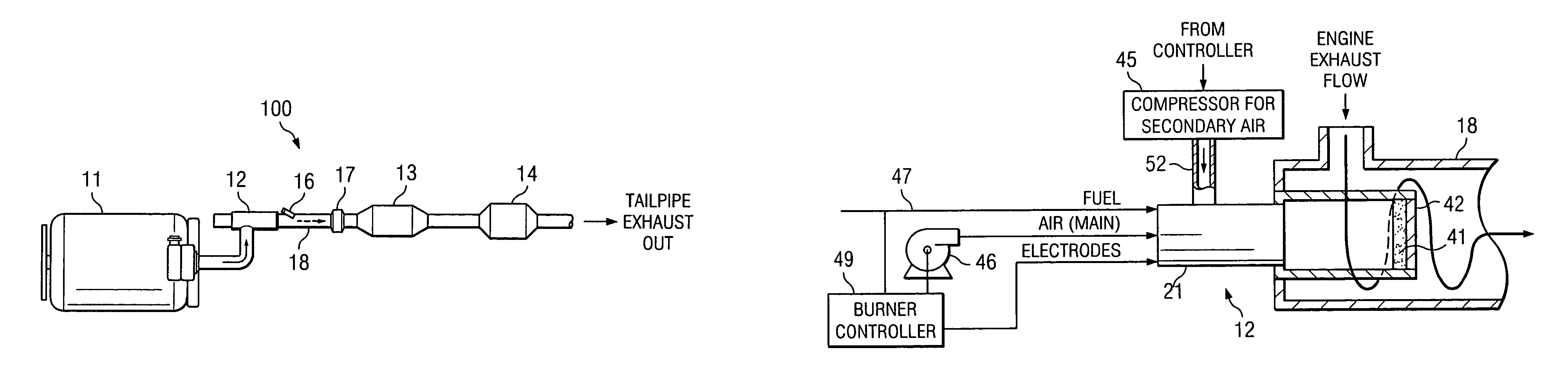
[0019]The invention described herein is directed to the design and operation of a burner device, which is used to maintain an appropriate temperature window of operation for emissions devices that require heat for proper operation and / or regeneration. The burner is typically used in the emissions system of a diesel engine, but is suitable for use in the emissions system of any lean burn internal combustion engine.

[0020]As explained below, the power output of the burner is variable to allow for higher temperatures during NAC regeneration or desulfation. The burner provides controllable main air flow and provides a large turn-down ratio, that is, a wide range of stable AFR (air-to-fuel ratio) and flow operation.

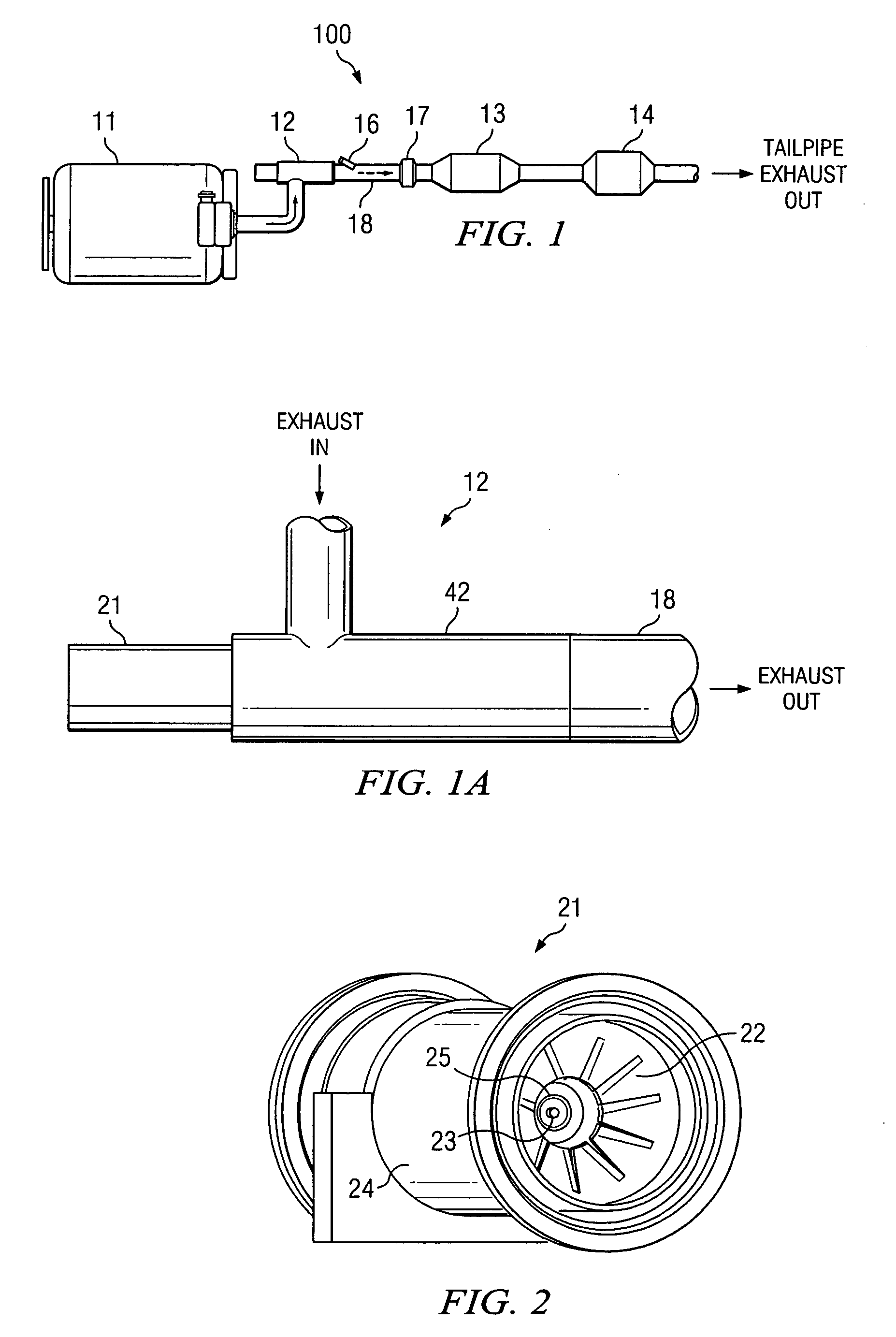
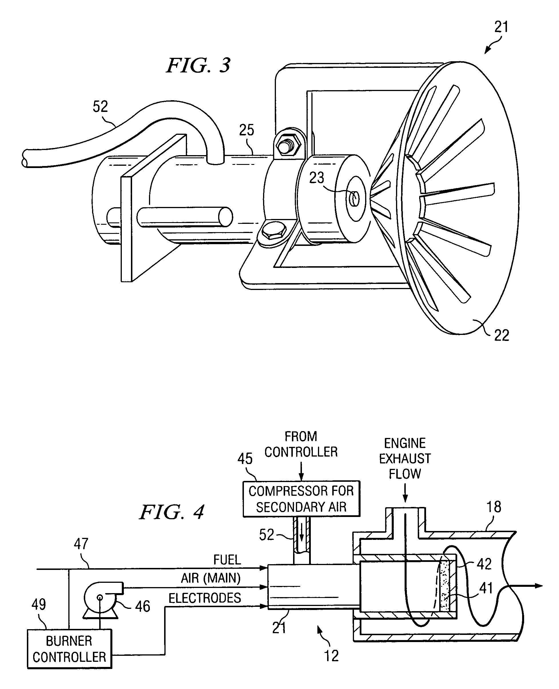
[0021]FIG. 1 illustrates an emissions system 100 for a diesel engine 11, having a burner 12 in accordance with the invention. System 100 is a “post combustion” emissions system, in that it is located downstream of engine 11 and treats exhaust from engine 11. System 100 is a sin...


PUM


Abstract

A burner for use in the emissions system of a lean burn internal combustion engine. The burner has a special burner head that enhances atomization of the burner fuel. Its combustion chamber is designed to be submersed in the engine exhaust line so that engine exhaust flows over the outer surface of the combustion chamber, thereby providing efficient heat transfer.

Description

RELATED PATENT APPLICATION[0001]This application claims the benefit of U.S. Provisional Application No. 60 / 498,319, filed Aug. 27, 2003 and entitled “Diesel Fuel Burner for Diesel Emissions Control System.”GOVERNMENT LICENSE RIGHTS[0002]The U.S. Government has a paid-up license in this invention and the right in certain circumstances to require the patent owner to license others on reasonable terms as provided for by the terms of Subcontract No. NREL-NCl-31024-02 under Contact No. DE-AC36-98G010337 for the U.S. Department of Energy.TECHNICAL FIELD OF THE INVENTION[0003]This invention relates to emissions systems for internal combustion engines, and more particularly to using a burner in conjunction with such emissions systems.BACKGROUND OF THE INVENTION[0004]Internal combustion engines are a major contributor to harmful emissions. Internal combustion engines dominate land transportation propulsion—cars, trucks, off-highway vehicles, railroad, marine, motorcycles—as well as provide m...

Claims


Application Information

Patent Timeline
Patent Type & Authority Patents(United States)
IPC IPC(8): F01N3/00
CPCF01N3/025F01N13/011F01N3/0842F01N3/2033F01N3/32F01N3/38F01N13/009F01N3/0256F01N3/035F01N3/0814F01N2240/14F01N2610/03Y02T10/26Y10S55/10Y10S55/30Y02T10/12
Inventor WEBB, CYNTHIA C.MATHIS, JEFFREY A.
Owner SOUTHWEST RES INST
Why Eureka
Try Eureka