
Integrated dispenser

a dispenser and integrated technology, applied in the direction of liquid transferring devices, instruments, movable measuring chambers, etc., to achieve the effect of greatly reducing the risk of contamination of contents

Active Publication Date: 2006-04-25
SHERK WILLIAM M JR
View PDF17 Cites 19 Cited by
  • Summary
  • Abstract
  • Description
  • Claims
  • Application Information

AI Technical Summary

Benefits of technology

[0010]The present invention satisfies these needs by integrating the fluent material to be dispensed with an inexpensive, simple-to-use device such that consistent, repeatable quantities of the fluent material can be dispensed by an untrained operator. By having the operator avoid all contact with the fluent material contents, the risk of contamination to the contents is greatly reduced.
[0012]Optionally, the dispenser is of predominantly plastic construction. In the present context, the dispenser is “predominantly” plastic in that the bulk of the housing making up its structure is plastic, while it will recognized by those skilled in the art that discrete components, such as the biasing spring and pin making up the hinge, could be other materials, such as metal. At least one portion may be of transparent plastic to facilitate visual identification of the amount of fluent material remaining in the dispenser. For example, the reservoir may be made from a transparent plastic, and may further include one or more optical treatments, such as a light filter, to inhibit ultraviolet breakdown of the fluent material contents due to exposure to sunlight or the like. The light filter can be made from, for example, a low emissivity coating or colorations in the transparent plastic. Labels (for identification of the fluent material product contained within the dispenser) can be adhered to the dispenser, and may include viewing ports to achieve protection against the light while still providing visual identification of the amount of fluent material remaining in the dispenser. For example, a vertically elongate cut-out in the label could allow a user to visually identify remaining product (thus making it readily apparent that it is time for the user to purchase more product), but block out a majority of the light. Similarly, the label can include die cut portions such that the user can selectively peel back the part of the label circumscribed by the die cut to be able to visually ascertain how much product remains. The sealing configuration of the disposable dispenser arises out of a connection between a cover through which the fluent material may be added to the reservoir and a fill aperture located in the reservoir.
[0015]In another option, the reservoir and actuation mechanism together form a single housing such that the two halves are of relatively equal size, shape and volume. In this configuration, the dispenser may further include a pair of cutoff members for the storage compartment, one extending from the reservoir and the other extending from the actuation mechanism such that they can overlap one another. Preferably, the apertures in the two cutoff members substantially align while the dispenser is in its first actuation position so that the fluent material from the storage compartment can pass through the flowpath formed by the aligned apertures and into to the discharge compartment. When the dispenser is in the second actuation position, the storage compartment discharge apertures are substantially misaligned such that flow of the fluent material from the storage compartment to the discharge compartment is impeded. In addition, the dispenser may further comprise cutoff members in the discharge compartment that are configured similar to those of the storage compartment mentioned above, such that the discharge compartment cutoff members are configured to overlap one another at least during one of the first or second actuation positions. Selectively aligned / misaligned apertures in each of the discharge compartment cutoff members function to either allow or impede fluent material flow out of the discharge compartment.
[0019]The integrated dispenser has numerous consumer benefits. For example, the material and the dispenser are provided in tandem, thus there is no need for the consumer to fill or otherwise transfer material to the dispenser. The dispenser is sealed to protect against contamination and to extend the shelf-life of the fluent material. The dispenser also, through a closure detent on the mounting base, has a safety lock to prevent accidental discharge of the fluent material contents, allowing the dispenser to be free standing. The size and ergonomic features of the dispenser allow it to be used with one hand, thus facilitating use by individuals with otherwise limited capacity to dispense a predetermined quantity of fluent material product. Other features, such as a “time to buy” view hole, tracking information and ingredient labeling and required information add to its utility. The dispenser can provide appropriate dosages within very close tolerances, and the dispensing procedures are similar for all materials by use within a particular animal or human category. The integrated dispenser also has numerous benefits to the retail trade, such as consistent packaging by product category, uniqueness, easy to explain use directions and breadth of product line.

Problems solved by technology

As such, a dispenser configured to sealingly contain fluent material necessarily excludes devices that are equipped with lids, covers and caps that can be repeatedly connected to or removed from their complementary access ports on the dispenser, even if the device is otherwise not easily disassembled.

Method used


Image

  • Integrated dispenser
  • Integrated dispenser
  • Integrated dispenser

Examples


Embodiment Construction

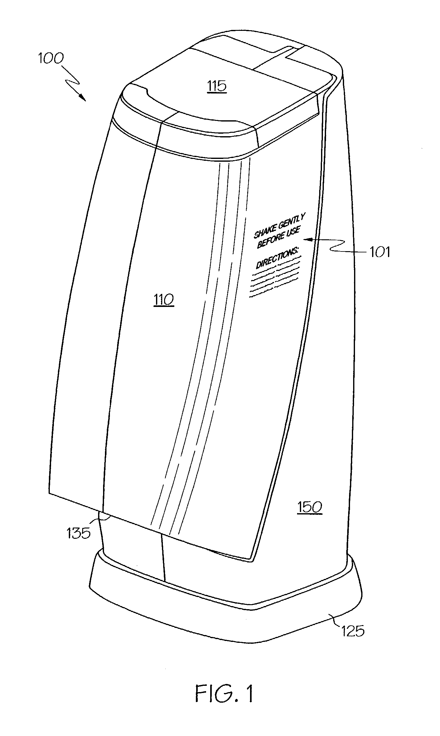
[0048]Referring initially to FIG. 1, a dispenser 100 according to an embodiment of the present invention is shown. Dispenser 100 includes a reservoir 110 attached to an actuation mechanism 150, a cover 115 attached to reservoir 110, a mounting base 125 and engaging lip 135. Mounting base 125 is removable from the dispenser 100. Printed indicia 101 (such as directions, warning labels, ingredient lists or the like) may be applied on the external surface of dispenser 100. The outer edges and corners of dispenser 100 can be rounded as shown to impart improved aesthetic and user handling features. It will be appreciated by those skilled in the art that the remaining embodiments may include similar attributes, even if not shown in the figures.

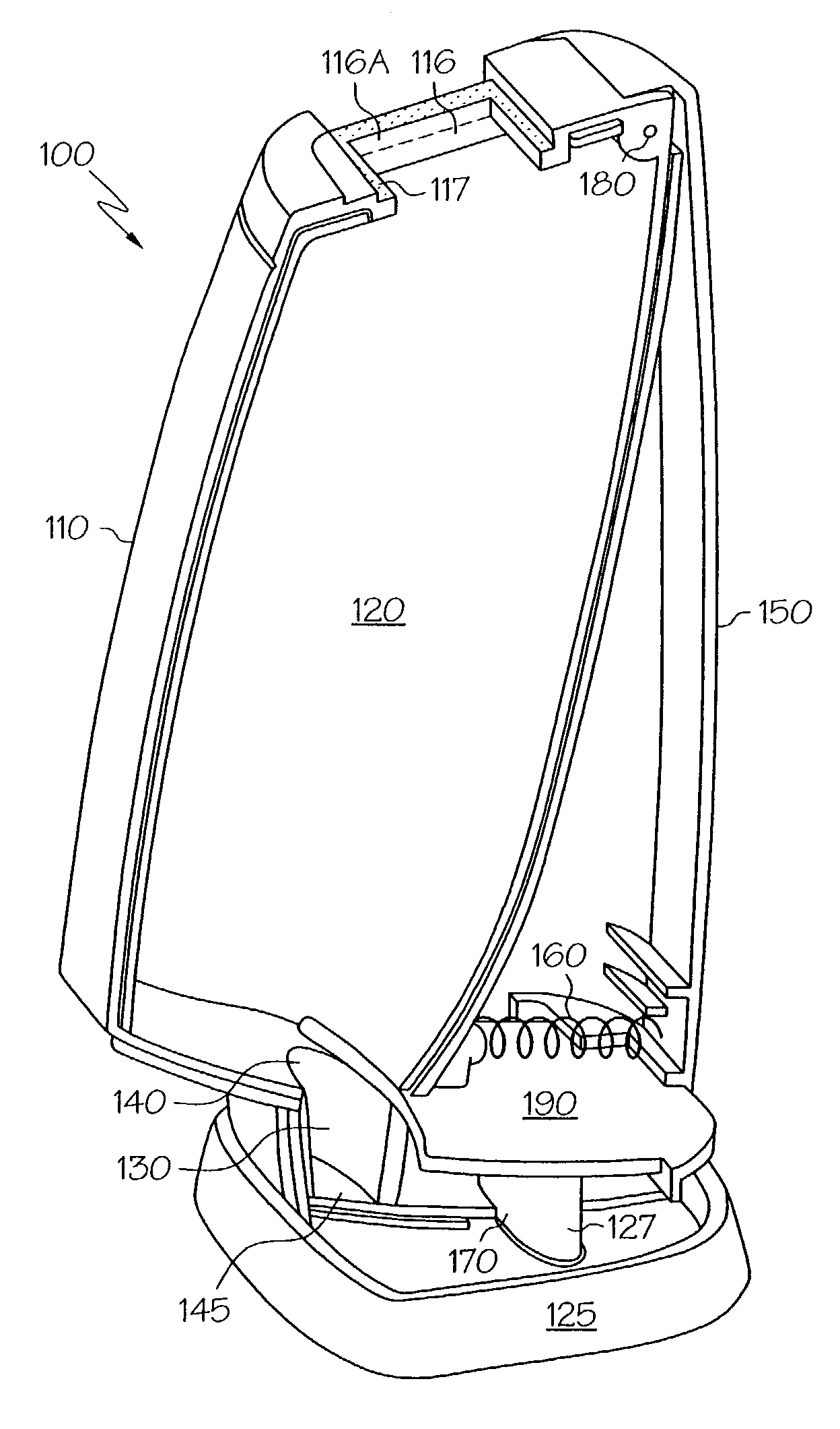
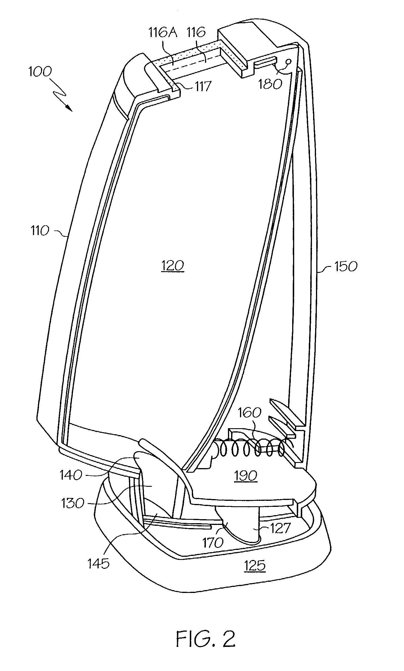
[0049]Referring next to FIGS. 2 and 3, cutaway views highlight the internal features of the reservoir 110 and the actuation mechanism 150. Reservoir 110 includes a storage compartment 120 into which fluent material can be poured through aperture 116 ...


PUM


Abstract

A dispenser for powdered, granular or related fluent materials. The dispenser includes a reservoir and an actuation mechanism that together define a housing, or enclosure. The reservoir sealingly contains a fluent material such that the contents are not easily contaminated or tampered with. User-imparted relative movement between cooperating parts of the actuation mechanism and reservoir enables a predetermined and repeatable quantity of the fluent contents to be discharged from the dispenser and onto a desired area, such as a food product. The dispenser is configured as a disposable device such that, after depletion of the fluent material contents arising out of a multiplicity of uses, it can be thrown away.

Description

[0001]This application claims the benefit of U.S. Provisional Application No. 60 / 376,915 filed May 1, 2002.BACKGROUND OF THE INVENTION[0002]The present invention relates generally to a device for dispensing a metered amount of powdered or granular material, and more particularly to a sealed, hand-held disposable dispenser for consistent dosing of the powdered or granular material such that upon depletion of the contents, the dispenser may be thrown away.[0003]Free-flowing powdered and granular substances (alternately referred to as part of a larger class known as fluent materials) are used extensively for myriad applications, and dispensers for such materials are well-known in the art. Examples include devices configured to discharge gunpowder, salt, sugar, spices, powdered dairy creamer or the like. Some of these devices dispense a metered, or predetermined amount of fluent material, while others permit the operator to determine how much of a desired product is dispensed.[0004]An i...

Claims


Application Information

Patent Timeline
IPC IPC(8): G01F11/28G01F11/18G01F11/24
CPCG01F11/24G01F11/18
Inventor SHERK, JR., WILLIAM M.CHAN, EDWINPERRY, MARCOSHONFELD, RICHARD C.
Owner SHERK WILLIAM M JR
Learn More