Method and apparatus for cake-forming granular-bed filtration

Active Publication Date: 2006-04-25
ARTHUR M SQUIRES IRREVOCABLE TRUST
View PDF20 Cites 9 Cited by
  • Summary
  • Abstract
  • Description
  • Claims
  • Application Information

AI Technical Summary

Benefits of technology

[0017]I have discovered a panel arrangement for cake-forming granular-bed filtration affording a significant increase in filtration capacity over the prior art while at the same time reducing the pressure loss in the filtered gas. I provide below a table comparing capabilities of several approaches to cake-forming gr

Problems solved by technology

This pressure drop cannot be allowed to increase without limit, for two reasons: an unduly large pressure drop would increase cost for gas-compression beyond an economic limit and would impose a force upon the filter cake sufficient to break off chunks of the cake, driving these deep into the granular bed and harming filtering efficiency.
Commercial-scale panel-bed-filter modules have now successfully cleaned hot gaseous products of combustion of both coal and wood waste, hot gas from cement production, and hot gas from electrometallurgical manufacture of ferrosilicon (this latter gas, containing a fine silica fume, is particularly difficult to clean).
This excellent filtration performance has been confirmed in tests of an installation comprising 27 substantially identical modules receiving gaseous products of combustion at 190° C. from a

Method used


Image

  • Method and apparatus for cake-forming granular-bed filtration
  • Method and apparatus for cake-forming granular-bed filtration
  • Method and apparatus for cake-forming granular-bed filtration

Examples


Embodiment Construction

[0041]In the several figures, like reference numerals refer to like parts having like functions.

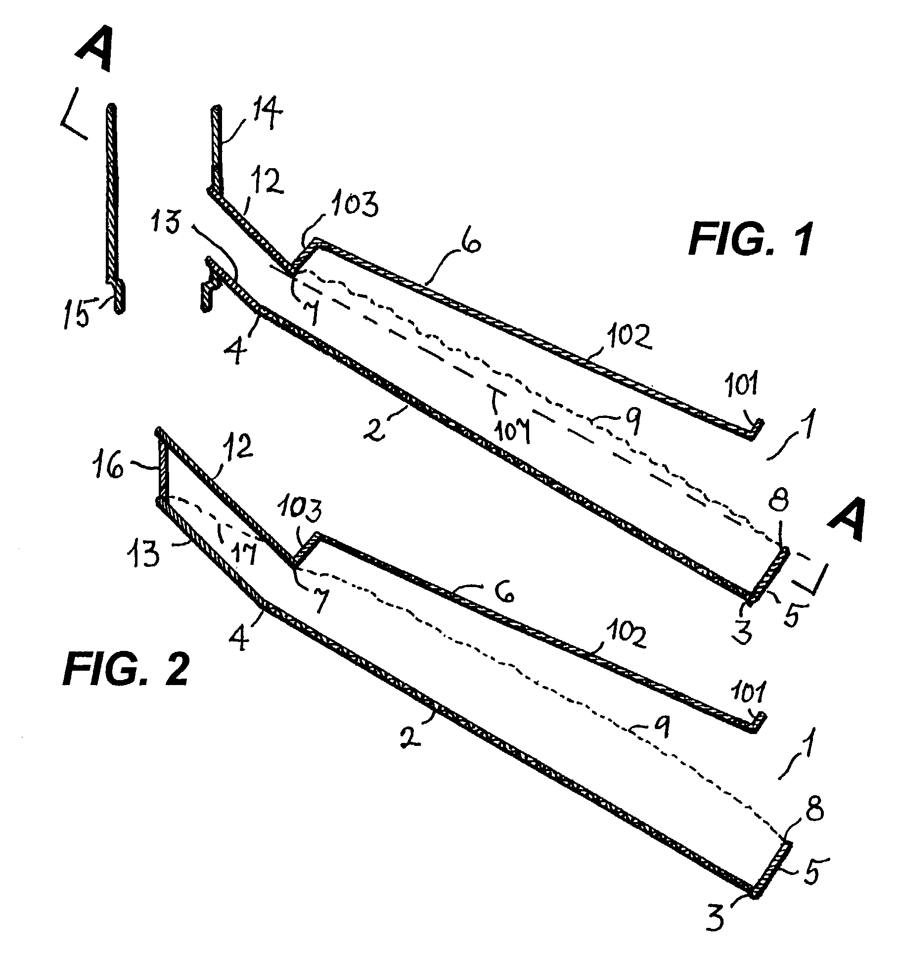
[0042]FIG. 1 is a vertical section through an individual filter tray 1 (absent granular material), in which there is a granular-material-supporting porous plate 2 inclined at an angle to the horizontal and having a lower, outer edge 3 and an upper, inner edge 4. In FIG. 1, plate 2 is shown as a screen with openings smaller than the granular material to be retained. Other permeable materials may sometimes be preferred for use in plate 2. For example, in a filter-tray panel intended to filter gas at a temperature beyond 1,000° C., use of a porous sintered ceramic plate is advantageous. For retaining granular medium upon plate 2, nonporous plate 5, articulating with edge 3, presents an upper edge 8 for retaining the outer edge of a bed of granular medium that will rest upon plate 2 (whose face will be approximately as shown by dashed curvilinear line 9 in FIG. 1). Nonporous plate member 6 co...


PUM

PropertyMeasurementUnit
Fractionaaaaaaaaaa
Fractionaaaaaaaaaa
Fractionaaaaaaaaaa

Abstract

There is provided a granular-bed filter for cleaning a gas containing fine particulate matter (“dust”). A multiplicity of vertically disposed filter trays are assembled to form a “panel.” In each filter tray, an inclined porous plate supports a bed of granular material. Each bed presents an inclined gas-entry face that receives gas from a vertically-disposed dusty-gas-distribution compartment nearby the face's lower edge. A filter cake forms upon the gas-entry face. Preferably, the bed's depth is substantially the same at its upper and lower edges. Cleaned gas leaves a tray across the porous plate and flows into a vertically-disposed cleaned-gas-collection compartment. After an interval of filtration, gas-entry faces are renewed by producing en masse displacement of the material respecting the supporting plates, the displacement producing a spill of a surface layer from each gas-entry face. The displacement is preferably accomplished by causing the support plates to move sharply upward (e.g., as may be caused by an upward blow of a hammer). The displacement may also be caused by subjecting the panel to a reverse transient surge flow of gas (i.e., a “puff-back”). After face renewal, granular material descends by gravity from an elevated source to make good loss of the material from the faces.

Description

[0001]This application claims the benefit of U.S. Provisional Application No. 60 / 332,543, filed Nov. 26, 2001.FIELD OF THE INVENTION[0002]The invention relates to the filtering of fine particulate matter (“dust”) from a gas.BACKGROUND OF THE INVENTION[0003]An old idea is to treat a gas and a granular solid material by causing the gas to flow in the horizontal direction across a bed of the solid material disposed in a “panel” that has often been tall in comparison with its width in the direction of gas flow. Often, the “panel bed” has been held in place by louvered walls that resembled Venetian blinds. My U.S. Pat. No. 4,006,533 (Feb. 8, 1977) cites early art and is incorporated by reference in the instant application.[0004]Some designs called for continuous or intermittent motion of granular material downward through the panel, fresh material being supplied at the panel's top and “spent” material being withdrawn at its bottom. A representative recent proposal along this line is to b...

Claims


Application Information

Patent Timeline
IPC IPC(8): B01D45/00
CPCB01D46/30B01D46/0075B01D46/76
Inventor SQUIRES, ARTHUR M.
Owner ARTHUR M SQUIRES IRREVOCABLE TRUST
Why Eureka
Try Eureka