

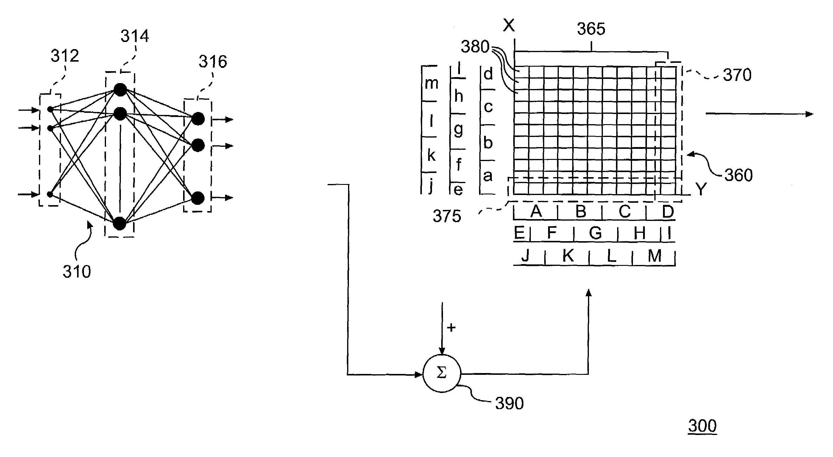
Engine control system using a cascaded neural network
a neural network and control system technology, applied in the direction of adaptive control, electric control, instruments, etc., can solve the problems of not being ideally suited to all such applications, not being able to control a multi-variable input and output system, and not being able to render control in real time for an actual physical system
- Summary
- Abstract
- Description
- Claims
- Application Information
AI Technical Summary
Benefits of technology
Problems solved by technology
Method used
Image

Examples
Embodiment Construction
[0013]For the purposes of promoting an understanding of the principles of the invention, reference will now be made to the embodiments illustrated in the drawings and specific language will be used to describe the same. It will nevertheless be understood that no limitation of the scope of the invention is thereby intended. The invention includes any alterations and further modifications in the illustrated devices and described methods and further applications of the principles of the invention which would normally occur to one skilled in the art to which the invention relates.
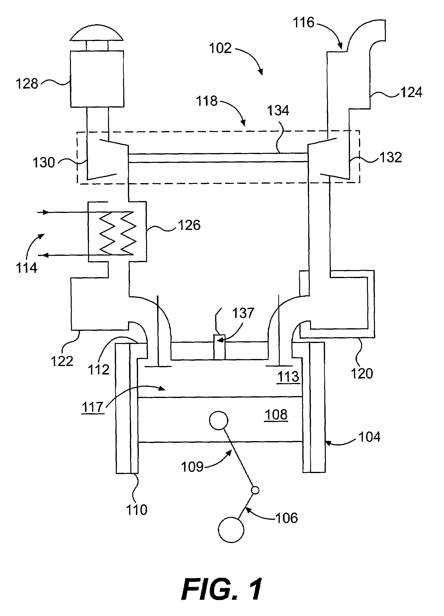
[0014]With reference to FIG. 1, embodiments of the present invention are adapted to monitor and control an engine. As shown in FIG. 1, an engine 102 includes an air intake system 114, an exhaust system 116, a combustion system 117, and a turbocharger 118. The air intake system 114 may include an air filter or cleaner 128, an aftercooler 126, and an air intake manifold 122. The exhaust system 116 may include an ...
PUM
 Abstract
Description
Claims
Application Information