Failure diagnostic system for fuel vapor processing apparatus

a technology of failure diagnostic system and which is applied in the direction of instruments, machines/engines, transportation and packaging, etc., can solve the problems of fuel vapor may leak to the outside, the failure of fuel vapor processing apparatus to treat fuel vapor properly, and the trouble of fuel vapor leakage, etc., to achieve positive diagnosis in a short time

Inactive Publication Date: 2006-05-02
AISAN IND CO LTD
View PDF18 Cites 37 Cited by
  • Summary
  • Abstract
  • Description
  • Claims
  • Application Information

AI Technical Summary

Benefits of technology

[0015]The present invention has been accomplished in view of the above-mentioned circumstances and it is an object of the invention to provide a failure diagnostic system for a fuel vapor processing apparatus which failure diagnostic system can minimize the leakage of fuel vapor to the outside at the time of diagnosis and permits diagnosis positively in a short time even at a high temperature.
[0016]It is another object of the present invention to provide a canister provided with a diagnosing functional component integrally, the canister being compact as a whole and difficult to be influenced by vibration.
[0017]It is a further object of the present invention to provide a pump module for use in failure diagnosis of a fuel vapor processing apparatus wherein an orifice is disposed always in a vertex position in a mounted state of the pump module on a vehicle, thereby preventing blocking of the orifice and permitting an accurate execution of failure diagnosis.

Problems solved by technology

In this type of a treatment system, if the flow path from the fuel tank to the intake passage should be perforated in a certain position for some reason or other or if a sealing defect should occur in a pipe joint portion, there is a fear that fuel vapor may leak to the outside, and it is impossible to treat the fuel vapor properly.
In this diagnostic system, when the internal pressure of the flow path once applied becomes lower than a predetermined value, it is determined that there is a leakage trouble in a fuel vapor processing apparatus.
Generally, however, the space for mounting various components in a vehicle is limited.
However, in the failure diagnostic system disclosed in Japanese unexamined patent publication No. 2003-155958, the interior of the flow path is pressurized, so if the flow path should be perforated, the application of pressure may rather cause leakage of fuel vapor to the outside through the hole.
However, even if the reduced pressure method is adopted, a large amount of fuel vapor is developed in the fuel tank when the temperature is high.
Accordingly, even if the pressure is reduced in this state, the internal pressure of the flow path is difficult to become negative and it takes much time for failure diagnosis.
But, if diagnosis is not performed at a high temperature, the diagnosis is less frequently performed accordingly.
This is contrary to the demand for early diagnosis upon occurrence of a failure or trouble.
In this state, for example, if the canister is attached to a vehicular frame through a bracket, the pump module will undergo vibration during vehicular running and vibrate, with consequent fear of breaking in the connection between the canister and the pump module.
Thus, there has been a problem in point of reliability as a diagnostic system.
If the orifice is thus positioned low, there is a fear of the orifice being plugged up with dust, water, fine adsorbent powder, intra-pipe oil, plastic extract, or assembling oil.
Once the orifice is thus plugged up, it is no longer possible to effect diagnosis with a high accuracy.

Method used


Image

  • Failure diagnostic system for fuel vapor processing apparatus
  • Failure diagnostic system for fuel vapor processing apparatus
  • Failure diagnostic system for fuel vapor processing apparatus

Examples


first embodiment

[First Embodiment]

[0050]A failure diagnostic system for a fuel vapor processing apparatus according to a first embodiment of the present invention will be described hereinafter with reference to the accompanying drawings.

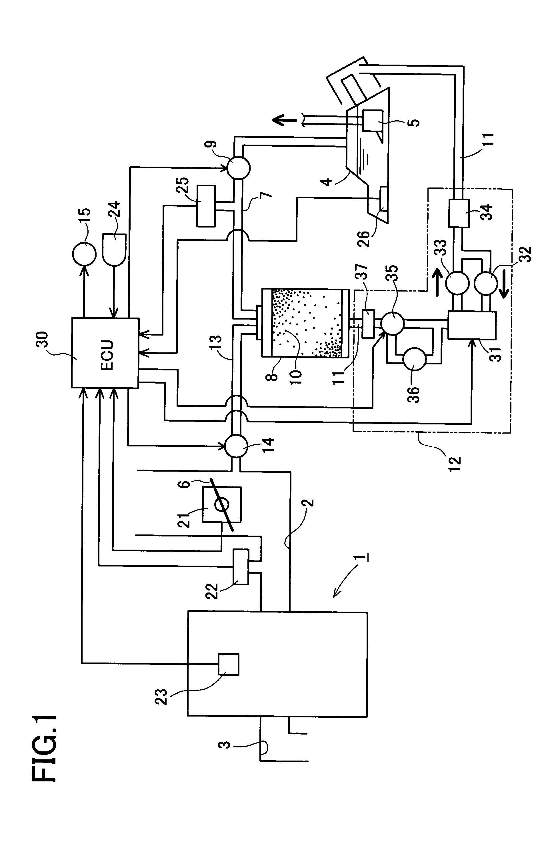
[0051]FIG. 1 is a schematic construction diagram of the fuel vapor processing apparatus and a failure diagnostic system therefor embodying the present invention, which are mounted on an automobile. An engine 1 mounted on the automobile is provided with an intake passage 2 for the intake of outside air and an exhaust passage 3 for the discharge of exhaust gas. For combustion in a combustion chamber (not shown) of the engine 1, fuel stored in a fuel tank 4 is fed into the combustion chamber by a predetermined fuel supply system including a fuel pump 5.

[0052]A throttle valve 6 adapted to be opened and closed for adjusting the amount of intake air is disposed in the intake passage 2, and a throttle sensor 21 for detecting an opening degree (throttle angle) TA of the thr...

second embodiment

[Second Embodiment]

[0092]A fuel vapor processing apparatus including a canister and a failure diagnostic system therefor according to a second embodiment of the present invention will be described in detail hereinafter with reference to the accompanying drawings.

[0093]FIG. 5 is a schematic construction diagram of the fuel vapor processing apparatus and the failure diagnostic system in the second embodiment both mounted on an automobile. In FIG. 5, the same components as in the first embodiment are identified by the same reference numerals as in the first embodiment, and explanations thereof will be omitted.

[0094]In this embodiment, a vehicle speed sensor 27 for detecting a vehicle speed SPD of the automobile is provided in the automobile. In this embodiment, a throttle sensor 21, an intake pressure sensor 22, a rotational speed sensor 23 and the vehicle speed sensor 27 correspond to the operating condition detecting means for detecting operating conditions of an engine 1 and the aut...

third embodiment

[Third Embodiment]

[0121]A third embodiment of the present invention which embodies in a most preferred mode a pump module for use in diagnosing a fuel vapor processing apparatus according to the present invention will be described in detail below with reference to the accompanying drawings.

[0122]A schematic construction of the fuel vapor processing apparatus and that of the failure diagnostic system according to this embodiment are shown in FIGS. 18 and 19. FIG. 18 shows a state in which a change-over valve is not supplied with an electric current, while FIG. 19 shows a state in which the change-over valve is supplied with an electric current.

[0123]A fuel vapor processing apparatus 101 in this third embodiment is installed in a vehicle with a gasoline engine mounted thereon, in which fuel vapor developed in a fuel tank 110 is trapped without release to the atmosphere. The fuel vapor processing apparatus 101 is provided with a canister 112 for trapping through a vapor line 111 the fu...


PUM


Abstract

In a failure diagnostic system for a fuel vapor processing apparatus, a processing flow path comprising a vapor line, a canister and a purge line is closed with a vapor control valve and a purge control valve. The interior of the processing flow path is reduced in pressure or pressurized by rotating an air pump of a pump module in a forward or reverse direction. An electronic control unit (ECU) closes the vapor control valve and the purge control valve to close the processing flow path after stop of the engine and, when the fuel temperature detected by a temperature sensor is lower than a predetermined value, reduces the internal pressure of the processing flow path through an air pump, then checks air-tightness of the interior of the processing flow path based on behavior of a vapor pressure detected by a pressure sensor. The ECU closes the processing flow path and, when the fuel temperature detected is not lower than the predetermined value, pressurizes the interior of the processing flow path through the air pump, then checks air-tightness of the processing flow path based on behavior of a vapor pressure subsequently detected.

Description

BACKGROUND OF THE INVENTION[0001]1. Field of the Invention[0002]The present invention relates to a fuel vapor processing apparatus wherein fuel vapor generated in a fuel tank is trapped or collected by a canister and the trapped fuel vapor is purged to an intake passage of an engine. More particularly, the present invention relates to a failure diagnostic system for checking a failure in air-tightness of a fuel vapor processing apparatus.[0003]The present invention also relates to a canister which is included as one component in a fuel vapor processing apparatus and which incorporates in a casing, an adsorbent for adsorbing fuel vapor.[0004]The present invention further relates to a pump module to be used in diagnosing a failure of a fuel vapor processing apparatus and more particularly to a pump module which permits failure diagnosis with a high accuracy.[0005]2. Description of Related Art[0006]As one of systems mounted on a vehicle, a fuel vapor processing apparatus has heretofore...

Claims


Application Information

Patent Timeline
Patent Type & Authority Patents(United States)
IPC IPC(8): G01M15/00G01M19/00F02D21/08F02M25/08G01M99/00
CPCF02M25/0809B60K2015/03514
Inventor HAYAKAWA, MASAMITSUHAYAKAWA, MASAHARU
Owner AISAN IND CO LTD
Why Eureka
Try Eureka