Light source device and image capturing device

a light source and image capturing technology, applied in the field of light source devices and image capturing devices, can solve the problems of deteriorating s/n ratio of obtained images, large size and large cost of image capturing devices, so as to improve incident efficiency and enhance incident efficiency of excitation light, the effect of enhancing the luminous energy of illumination ligh

Inactive Publication Date: 2006-05-02
FUJIFILM HLDG CORP +1
View PDF19 Cites 81 Cited by
  • Summary
  • Abstract
  • Description
  • Claims
  • Application Information

AI Technical Summary

Benefits of technology

[0007]The present invention has been made in consideration of the foregoing problems. It is an object of the present invention to provide a small, inexpensive and less heat-generating light source device and an image capturing device using the light source device.

Problems solved by technology

However, since the above-mentioned light source device including the xenon lamp, etc. is large and expensive, the image capturing device itself becomes large and expensive.
For this reason, in the endoscope provided with the solid-state image capturing element being disposed at an inserting portion to be inserted into a living body, there is also a problem that dark noise is generated due to the heat and the noise is included in output data, whereby an S / N ratio of an obtained image is deteriorated.

Method used


Image

  • Light source device and image capturing device
  • Light source device and image capturing device
  • Light source device and image capturing device

Examples


first embodiment

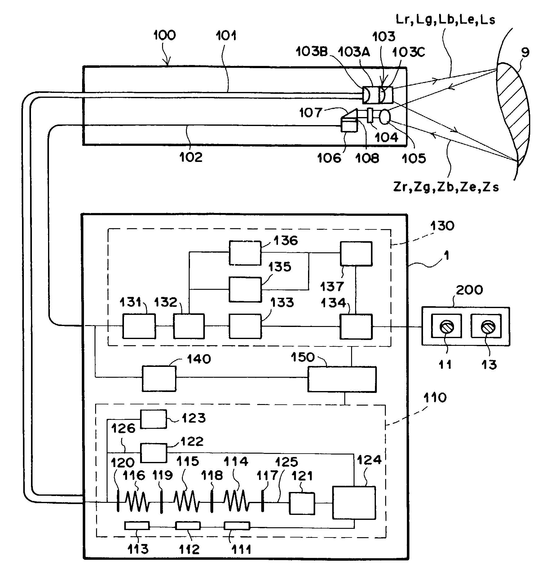
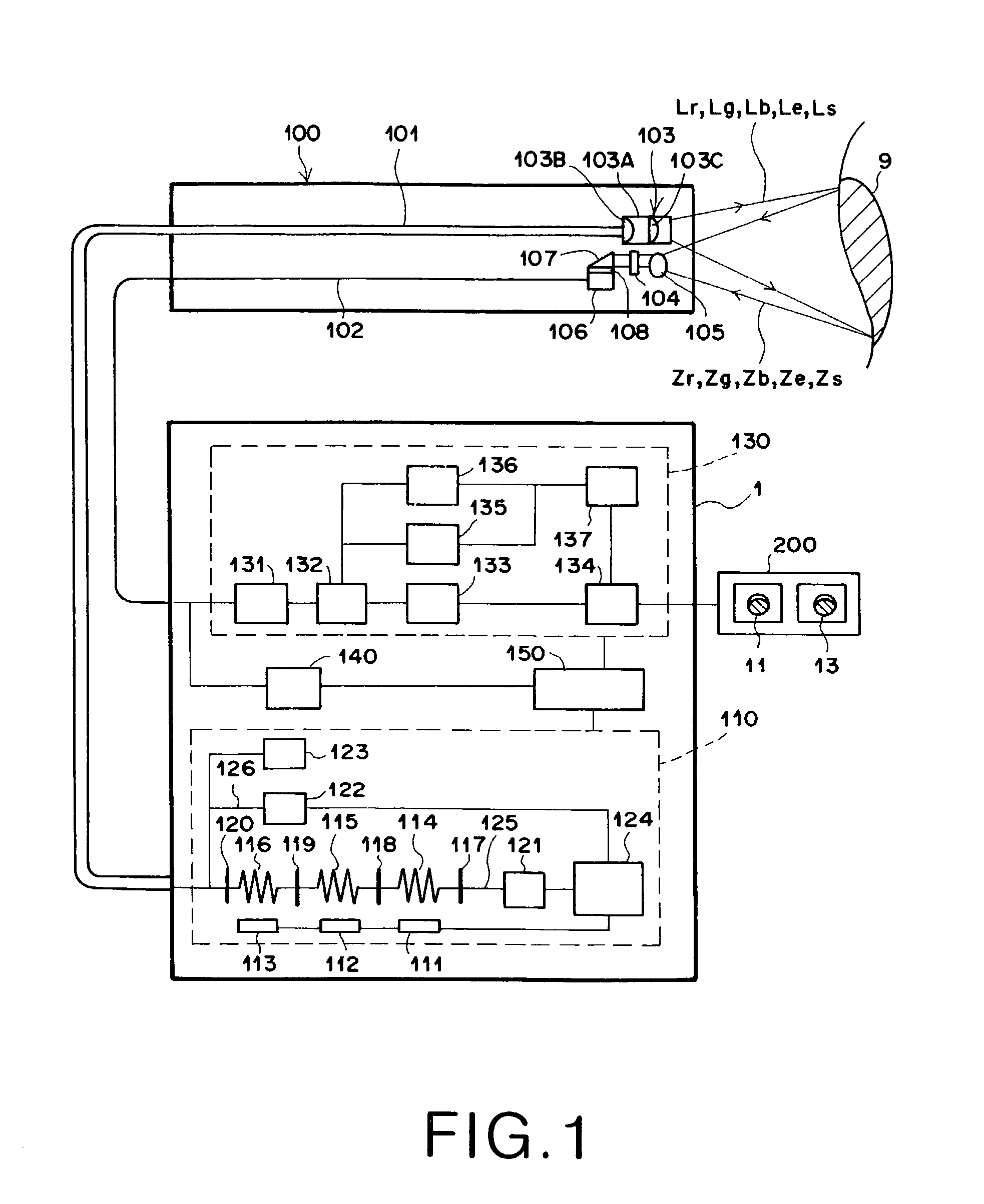
[0034]Now, embodiments of the present invention will be described with reference to the accompanying drawings. FIG. 1 is a schematic constitutional view showing a constitution of an endoscope using a light source device according to the present invention. As shown in FIG. 1, the endoscope adopts a frame sequential method, in which R light (red light) Lr, G light (green light) Lg and B light (blue light) Lb collectively being illumination light, sampling light (near infrared light) Ls and excitation light Le are sequentially irradiated on an observation area of a living body 9 and a reflected image being reflected by the observation area of the living body 9 and a fluorescent image generated at the observation area of the living body 9 are captured with a CCD image capturing element of a charge multiplying type, whereby an image of the observation area is displayed on a monitor as a color image. The endoscope includes an endoscope inserting portion 100 having the CCD image capturing ...

second embodiment

[0085]In the endoscope of the second embodiment, an illumination unit 110 includes light sources 171, 172 and 173 made of either SLD's or LD's for emitting ultraviolet light, and fluorescent fibers 174, 175 and 176 made of single fibers respectively connected to emitting end faces of the light sources 171, 172 and 173 for generating R light Lr, G light Lg and B light Lb by irradiation of the ultraviolet light.

[0086]Here, since emitting portions of the SLD's and the LD's have small diameters, the fluorescent fibers 174, 175 and 176 can be connected to the emitting end faces directly. In this way, it is possible to prevent reduction of incident efficiency of the ultraviolet light onto the fluorescent fibers 174, 175 and 176. As a result, it is possible to emit the R light Lr, the G light Lg and the B light Lb with more luminous energy.

[0087]Moreover, in the case of connecting the fluorescent fibers 174, 175 and 176 to the emitting end faces of the SLD's or the LD's, incident efficienc...


PUM


Abstract

A light source device for use in an image capturing device such as an endoscope capable of reducing size and cost, and preventing heat generation at an illuminated position. An illumination unit of the endoscope includes LED light sources for emitting ultraviolet light, fluorescent fibers for generating red, green and blue light respectively by irradiation of the ultraviolet light, a sampling light source, and an excitation light source. Upon capturing a normal image, the ultraviolet light is emitted sequentially from the LED light sources to cause the fluorescent fibers to generate the red, green and blue light. The light of each color is passed through a light guide and irradiated on an observation area of a living body. Thereafter, reflected images attributable to the light of each color are captured with a CCD image capturing element of a charge multiplying type, and captured images are displayed on a monitor.

Description

BACKGROUND OF THE INVENTION[0001]1. Field of the Invention[0002]The present invention relates to a light source device using a solid-state light-emitting element such as a light-emitting diode (LED), a super luminescence diode (SLD) or a laser diode (LD), and to an image capturing device using the light source device.[0003]2. Description of the Related Art[0004]Conventionally, image capturing devices such as an endoscope, which uses a solid-state image capturing element such as a charge-coupled device (CCD) for converting an optical image into electrical signals, have been utilized in the medical field for capturing an optical image of an observation area. Image data outputted from the solid-state image capturing device have an advantage that a plurality of people can observe the image data simultaneously by means of displaying the data on a monitor or the like. Moreover, the image data can be subjected to a variety of image processing prior to display, whereby it is also possible t...

Claims


Application Information

Patent Timeline
Patent Type & Authority Patents(United States)
IPC IPC(8): A61B1/07F21V8/00A61B1/04G02B6/00A61B1/06G02B23/26H01L27/148H04N5/225
CPCA61B1/0638H04N5/2256A61B1/07A61B1/0653H04N2005/2255H04N23/56H04N23/555
Inventor HAKAMATA, KAZUOTOIDA, MASAHIRO
Owner FUJIFILM HLDG CORP
Why Eureka
Try Eureka