Electric heater for the coupling head of a central buffer coupling

a technology of electric heater and central buffer, which is applied in the direction of heater elements, railway couplings, heating element shapes, etc., can solve the problems of local overheating, unsuitable use of soft solders with low melting points, and damage to the heating element, so as to facilitate the simple placement of the heating element, facilitate heat conduction, and use the effect of positioning

Inactive Publication Date: 2006-05-02
VOITH TURBO SCHARFENBERG
View PDF13 Cites 2 Cited by
  • Summary
  • Abstract
  • Description
  • Claims
  • Application Information

AI Technical Summary

Benefits of technology

[0012]The recess either being oriented substantially parallel to the faceplate of the coupling head or linear in accordance with this invention provides on the one hand useful positioning and on the other hand a beneficial geometric design that guarantees rapid heat conduction into the face of the coupling head.
[0013]The feature in accordance with this invention wherein the recess extends from the edge of the coupling head towards the inside of said head facilitates simple placement of the heating element into the coupling head after its mechanical completion.
[0014]The features of this invention that provides for heating elements disposed from both the right and left edges of the faceplate toward the inside of said faceplate or under the coupling bodies penetrating said faceplate promote quick and even heat conduction and distribution into the coupling head, particularly into said faceplate, which reduces thawing times.
[0015]By using removable fasteners for affixing the element to the coupling head in accordance with this invention, quick assembly and disassembly guarantee rapid installation, removal, and replacement of a defective heating element, which also helps to achieve shorter down times for vehicles when replacing the heating element.

Problems solved by technology

Only low-melting-point hard solders, such as expensive silver solders, can be used as hard solders, because there is a risk of damaging the heating element at high processing temperatures.
The use of soft solders with low melting points proved to be unsuitable because the melting temperature of the soft solder could be reached at the necessary heat output.
When soldering in the heating element, there is always the risk of local overheating and resulting destruction of the heating element before placement into service.
In addition, soldering in the heater without cavities in the filling material can be ensured only with considerable cost.
In the cavities to be avoided, there may be local overheating of the heater on the one hand, or moisture can penetrate during operation, which leads to corrosion.
Because the channel is made much wider than the diameter of the heating element for assembly reasons, there are undefined positionings of the heating element on the inside of the channel, which can lead to heat accumulation and overheating and consequently to destruction of the heating element.
In addition to potential damage of the installed heating element by the welding / soldering process itself, in the cavity for the heating element there is always the risk of the penetration of moisture and the resulting destruction of the heater.
An electric heater for central buffer couplings, whose heating element in the channel is filled with a silicon material that forms the outside covering and that is a free-flowing single-component material during filling which cross-links and hardens under the influence of humidity in the air at room temperature, is known from DE 296 11 148 U. Due to the relatively poor heat conduction λ=0.21 W / (m×K) and the poor temperature resistance of the elastic casting compounds that were previously available and used, overheating of the heating element can occur which leads to destruction of the casting compound and consequently to destruction of the heating element.
In addition, with the low surface strength of such casting compounds, there is the risk of penetration of foreign bodies and therefore of mechanical damage to the heating element.
Another disadvantage of the aforementioned designs is that replacing defective heating elements, since coiled tubing heating elements are generally used, is possible only by costly separation of the soldering seams or casting compound in the manufacturing plant or at a workshop.
After replacing defective heating elements, the systems that are used must again undergo costly manufacturing by further soldering / welding or casting.

Method used


Image

  • Electric heater for the coupling head of a central buffer coupling
  • Electric heater for the coupling head of a central buffer coupling

Examples


Embodiment Construction

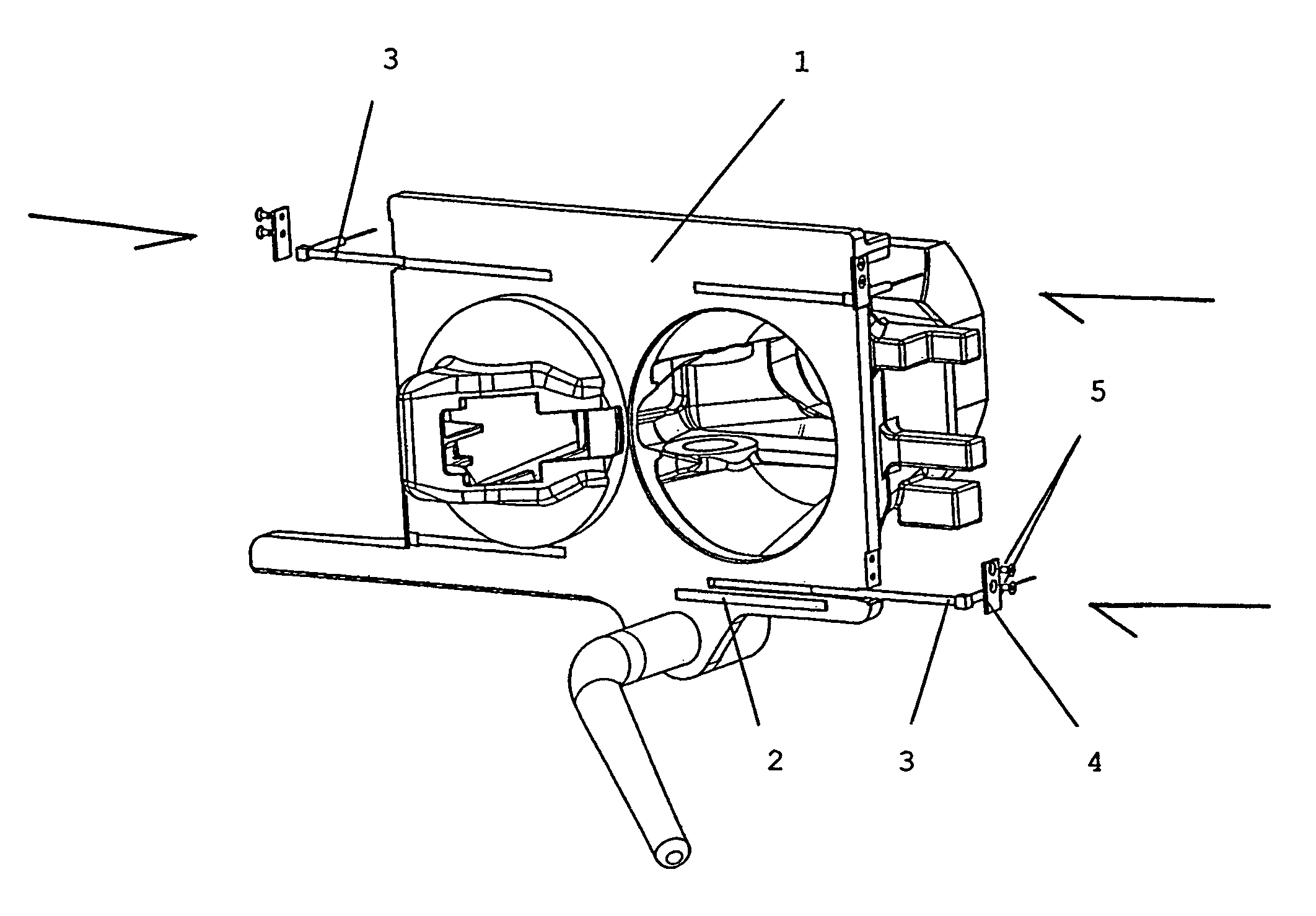
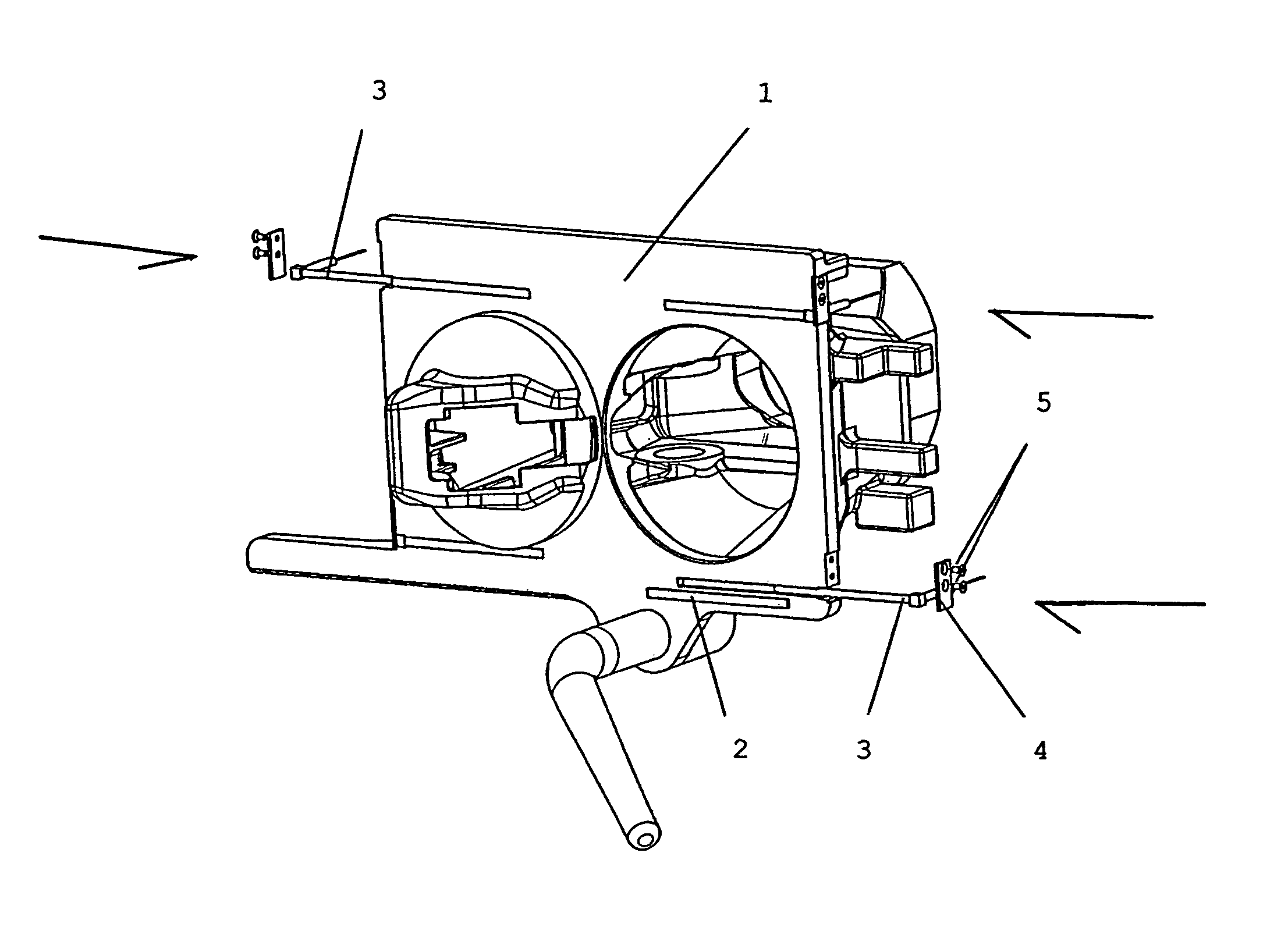
[0017]The invention is described in greater detail below based on an embodiment in reference to the drawing, in which FIGURE shows a perspective view of an electric heater for a central buffer coupling with heating elements that are installed and intended for installation.

[0018]Recesses in the form of channels are disposed in the faceplate of coupling head 1 of a central buffer coupling shown in FIGURE. The channels made in the faceplate in different orientations and at different distance dimensions are coverable or covered toward the front in the plane of the faceplate closure by face sheets 2. Face sheets 2 are placed in appropriate indentations and connected to the faceplate, preferably by hard soldering. The resulting recess / channels are intended to receive heating elements 3 and are precisely matched to each other with regard to their diameter dimension Each heating element 3 is fastenable after installation through a holding sheet 4 on coupling head 1 by means of removable fas...


PUM


Abstract

The invention relates to a heater for an electric central buffer coupling in which at least one heating element (3) is placed in a recess of the coupling head (1) and is covered toward the outside. To improve the transfer of heat from the heating element (3) into the coupling head (1) and to reduce the expense of assembling and dismantling the heating element (3), the recess is precision fitted to the diameter of the heating element (3) and the recess is constructed in such a way that after completion of the recess the heating element (3), including its seal to the front side, can be introduced into the recess and is to be removably affixed to the coupling head (1).

Description

[0001]The invention relates to an electric heater for the coupling head of a central buffer coupling in accordance with the generic part of this invention.BACKGROUND OF THE INVENTION[0002]Central buffer couplings have been used in series ET 420 urban railway multiple units in which an approximately semicircular channel, in which the electric heater is installed, is made in the buffer surface of the coupling head in the area of the centering ball and the inlet funnel. The heating element is intended to keep the face surface and coupling mechanism free of ice and snow in the winter and ensure the coupling function. The channel is sealed toward the outside by a hard solder, which forms a part of the buffer surface. Only low-melting-point hard solders, such as expensive silver solders, can be used as hard solders, because there is a risk of damaging the heating element at high processing temperatures. The use of soft solders with low melting points proved to be unsuitable because the me...

Claims


Application Information

Patent Timeline
Patent Type & Authority Patents(United States)
IPC IPC(8): H05B3/00B61G1/00B61G5/00H05B1/00B61G7/00
CPCB61G7/00H05B1/00
Inventor DITTMAR, GOETZBEHRENS, DIRK
Owner VOITH TURBO SCHARFENBERG
Why Eureka
Try Eureka