Slot antenna array using LTCC technology

Inactive Publication Date: 2006-05-02
ROBERT BOSCH GMBH
View PDF9 Cites 15 Cited by
  • Summary
  • Abstract
  • Description
  • Claims
  • Application Information

AI Technical Summary

Benefits of technology

[0007]It is advantageously possible for the feeder lines and the coupling slots to be surrounded at a fixed distance by plated-through contacts, the distance being smaller than a critical distance at which waveguide modes form. This shielding makes it possible to nail down, so to speak, the lines for the radiation.
[0017]On the whole, the embodiment forms according to the invention offer a completely planar design of the antenna array without the requirement of holes or cavities, a simple and inexpensive production using LTCC technology, a complete shielding of other circuit parts, and the recovery of stray fields. This increases the power emitted and consequently also the efficiency of the antennae.

Problems solved by technology

Also, the high permittivity impedes a release of waves toward open space.

Method used


Image

  • Slot antenna array using LTCC technology
  • Slot antenna array using LTCC technology
  • Slot antenna array using LTCC technology

Examples


Embodiment Construction

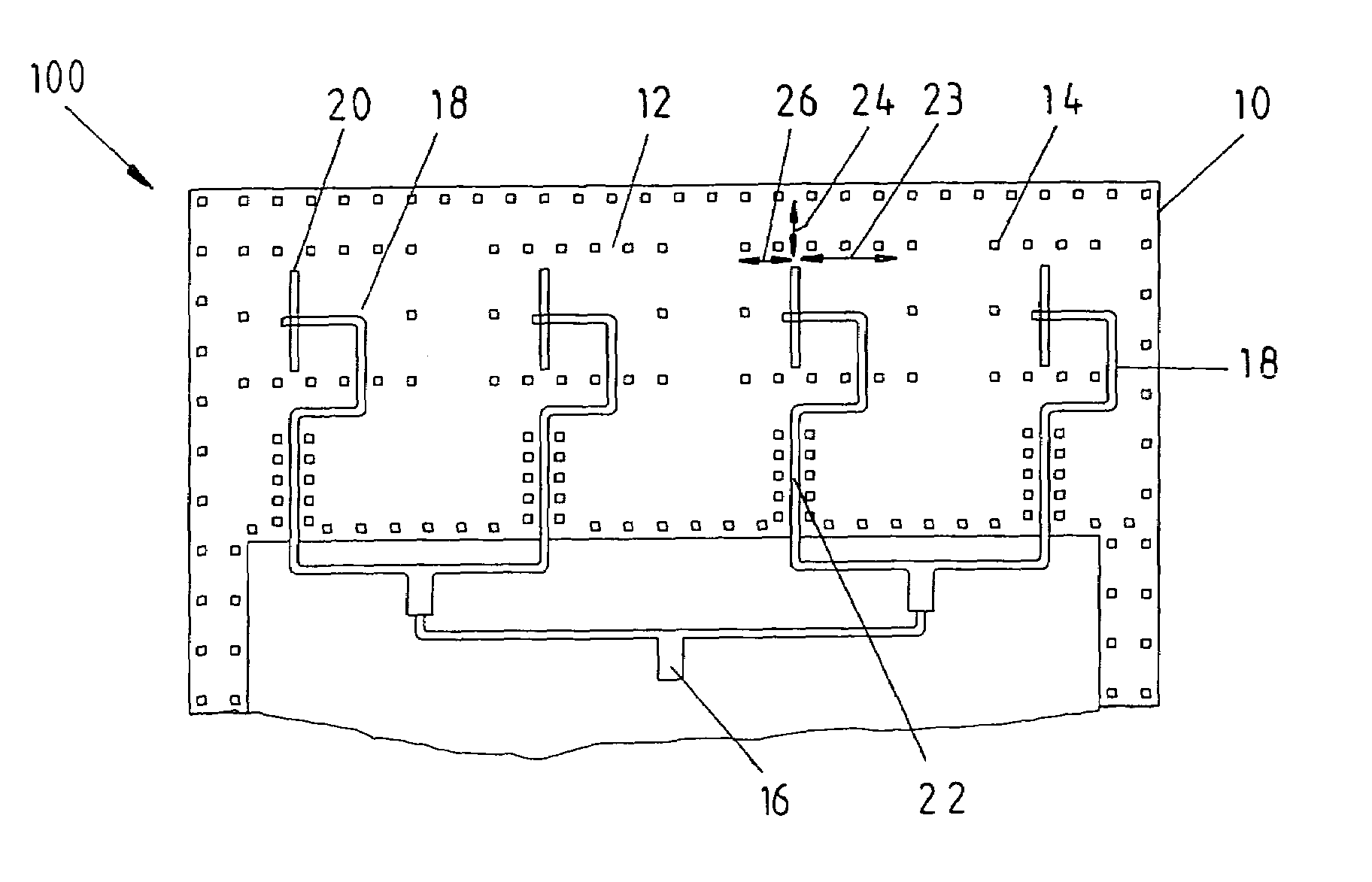
[0023]FIG. 1 shows a view of a planar antenna array 100 according to an exemplary embodiment of the invention. The antenna array 100 has an LTCC substrate 10 with an upper grounded layer 12 and a lower grounded layer that is not visible in the depiction in FIG. 1. A number of rectangular plated-through contacts 14 connect the upper grounded layer to the lower grounded layer.

[0024]The antenna array 100 also has a microstrip feeder network 16, which in the exemplary embodiment, supplies four embedded feeder lines 18 that each lead to one of four coupling slots 20 for emitting microwave radiation into open space. Between the feeder lines 18 and the feeder network 16, the LTCC substrate 10 has four coplanar waveguides 22. In the exemplary embodiment of FIG. 1, the plated-through contacts 14 enclose the coupling slots 20 with a distance 24 of approximately λ / 2 in the slot direction and with distances 26 and 28 of approximately 0.8*λ / 2 and 1.3*λ / 2 perpendicular to the slot direction.

[0025...


PUM


Abstract

In order to produce a planar antenna array in a radar sensor with a multitude of microstrip feeder lines and a multitude of coupling slots for emitting microwave energy into open space, which achieves a favorable antenna efficiency when embodied in a planar design using LTCC technology, the invention proposes embodying the feeder lines and the coupling slots in a multilayer ceramic substrate produced by means of the LTCC thick layer technique with an upper and a lower grounded layer, as well as enclosing the feeder lines and the coupling slots with plated-through contacts from the upper grounded layer to the lower one.

Description

[0001]This application is a 371 of PCT / DE03 / 03817 Nov. 18, 2003.BACKGROUND OF THE INVENTION[0002]The invention relates to a planar antenna array in a radar sensor for detecting objects in the vicinity of a motor vehicle, with a multitude of microstrip feeder lines and a multitude of coupling slots for emitting microwave energy into open space.[0003]The patent application EP 0685 930 A1 has already disclosed a radar sensor with a mount that is attached to a vehicle in order, for example, to determine the distance and relative speed of a vehicle driving forward. The radar sensor described therein contains an oscillator, a mixer, an amplifier, an antenna array for sending and receiving microwave radiation, and a receiver with evaluation electronics. An advantageous housing for a radar sensor of this kind has been disclosed, for example, by the patent application DE 199 04 303 A1.SUMMARY OF THE INVENTION[0004]The object of the invention is to disclose an antenna array of the type mentio...

Claims


Application Information

Patent Timeline
IPC IPC(8): H01Q1/38G01S7/03H01Q1/32H01Q13/10
CPCH01Q13/10H01Q1/38H01Q1/3233G01S7/032
Inventor SCHMIDT, EWALDVOITLAENDER, KLAUSGAIER, STEFANSEIDEL, JUERGEN
Owner ROBERT BOSCH GMBH
Why Eureka
Try Eureka