Solid state motor protector

a solid-state motor and protector technology, applied in emergency protection circuit arrangements, dynamo-electric components, relays, etc., can solve the problems of tripping protectors nine times faster during overload conditions, nuisance trip issues, etc., to reduce the “rate of temperature rise” prolong the initial trip time, and remove the resistance of the ptc component.

Active Publication Date: 2006-05-02
SENSATA TECH MASSACHUSETTS INC
View PDF17 Cites 8 Cited by
  • Summary
  • Abstract
  • Description
  • Claims
  • Application Information

AI Technical Summary

Benefits of technology

[0013]Removing resistance from the PTC component and reducing its “rate of temperature rise” extends the initial trip time at extreme percentage overloads, reducing nuisance trip operation during transient locked rotor conditions. Taken alone, this action results in loss of current sensitivity at low ampere levels, which would degrade locked rotor safety performance at minimum ambient, voltage and ampere conditions. According to the invention, the fixed resistor is added to produce the appropriate ultimate trip performance to carry normal operational ampere levels and adjust the current response curve at intermediate percentage overload conditions necessary for locked rotor safety across extreme voltage, ambient and commutation conditions.

Problems solved by technology

As a result, protectors cannot utilize the motor's internal ambient temperature to drive the tripping action to be effective since the accelerated winding's temperature rise will cause the winding insulation to melt prior to raising the motor protector's temperature mounted on the brush card.
With respect to Polymer PTC solutions, as alluded to above, the reduction of cross sectional area to achieve resistance requirements results in tripping the protector nine times faster during overload conditions due to increased rates of temperature rise.
This also results in nuisance trip issues during transient locked rotor conditions.
However, the cost of effectively blanking polymer PTC chips with proposed diameter to thickness ratios would be difficult with existing manufacturing technology.
Another complication relates to the phenomena of the polymer PTC experiencing torque performance degradation wherein the PTC resistance increases by some 40% after the initial switch and reset operation of the PTC element.
It is postulated that this is caused by carbon particles in the polymer not achieving 100% realignment.
The resistance shift can be even greater than 40% immediately after the supply voltage is removed producing greater transient motor performance degradation and nuisance trip conditions.

Method used


Image

  • Solid state motor protector
  • Solid state motor protector
  • Solid state motor protector

Examples


first embodiment

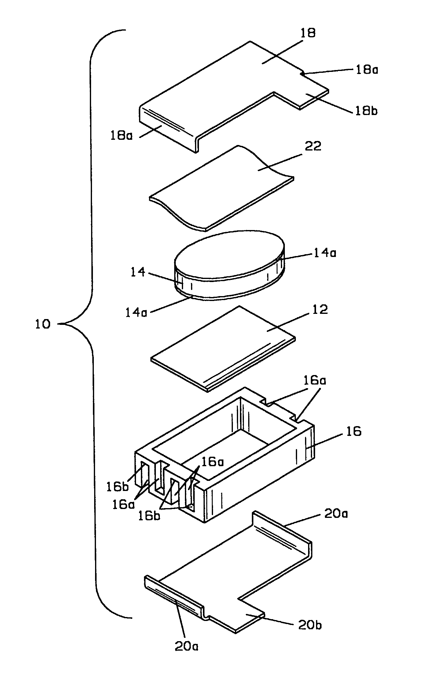
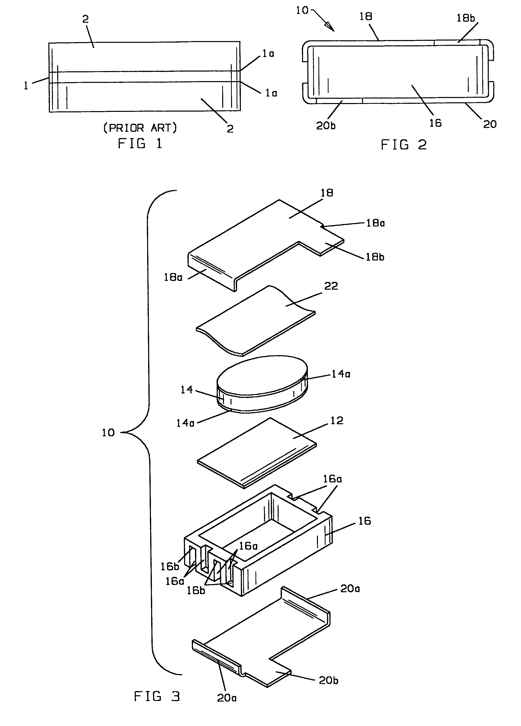
[0029]With reference to FIGS. 2 and 3, a motor protector 10 particularly useful with high voltage (e.g., 42 Vdc) automotive systems made in accordance with the invention, comprises a polymer PTC chip 12 having metal foil current collectors (not shown) on opposite face surfaces thereof electrically connected in series with a fixed resistance resistor 14 having contact surfaces 14a on opposite face surfaces thereof. A generally rectangular sidewall formed of electrically insulative material such as a thermoplastic polymer serves as an isolator 16 separating top and bottom terminal plates 18, 20, respectively, formed of suitable electrically conductive material such as nickel zinc plated steel. PTC chip 12, fixed resistor 14 and an electrically conductive spring 22 of steel, beryllium copper or other suitable material are aligned by the isolator and stacked between the terminals which are suitably attached to isolator 16 as by crimping sidewalls 18a, 20a, bending portions of the sidewa...

second embodiment

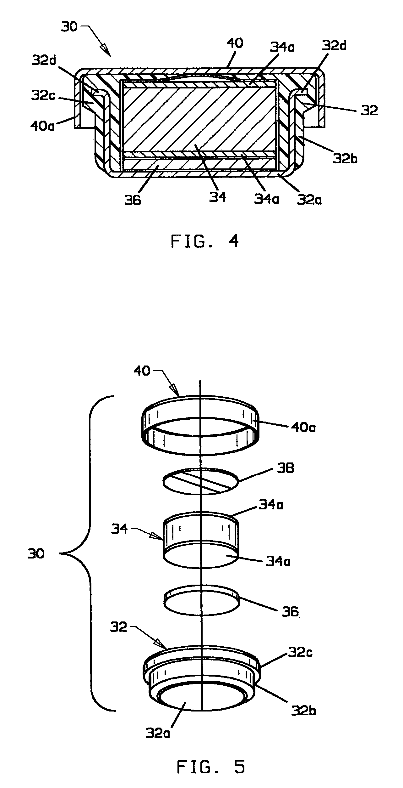
[0032]the invention is shown in FIGS. 4 and 5. Motor protector 30 is particularly useful for automotive applications employing small motors such as motors used for door locks. Motor protector 30 is a button cell type having an insert molded member 32 having a terminal portion 32a and a generally annular isolator portion 32b providing structural integrity to the package and an external electrical connection surface. A generally cylindrical fixed resistor 34 shown with suitable electrical contact surface 34a, generally cylindrical polymer PTC resistor element 36, having current collectors on opposed face surfaces but not separately shown for clarity of illustration, and a suitable electrically conductive spring member 38 are received within the cavity formed in insert molded member 32. An additional cup-shaped terminal 40 is received over the sub-assembly and crimped to the isolator portion 32b by bending the free distal end of sidewall 40a over the bottom surface of circumferential f...


PUM


Abstract

A solid state motor protector has a first PTC chip (positive temperature coefficient of resistivity) electrically connected in series relation with a second resistor having a generally fixed temperature coefficient of resistivity and mechanically coupled to the first resistor in close/direct thermal coupling. Another embodiment has a plate like isolator (52) formed with an opening receiving a polymer PTC chip (58) and having terminals (54, 56) which serve as fixed resistors. Yet another embodiment has an additional PTC resistor and a fixed resistor used in a motor reversing mechanism. Still another embodiment has a fixed resistor on either side of a PTC resistor for use in protecting the windings of a single phase motor. Another embodiment has a stack of polymer PTC resistor chips (82a–82d) with one chip serving as a voltage blocking chip and the other chip serving as fixed resistors.

Description

FIELD OF THE INVENTION[0001]This invention relates generally to protection devices for electric motors and more particularly to such protectors employing solid state protection PTC (positive temperature coefficient of resistance) elements.BACKGROUND OF THE INVENTION[0002]Electric motors utilize a variety of protectors to avoid degradation of the winding insulation during abusive locked rotor conditions. Permanent magnet motors applied in the automotive industry utilize bimetallic or polymer PTC protectors mounted on the brush card, which are connected in series with the motor windings. This arrangement promotes detection of elevated locked rotor versus normal running currents and increasing ambient temperature within the motor housing. The combination of internal I2r heating and increasing ambient temperature drives the protectors to interrupt the electric circuit which limits the winding temperature to an acceptable level.[0003]An example of a prior art polymer PTC protector partic...

Claims


Application Information

Patent Timeline
Patent Type & Authority Patents(United States)
IPC IPC(8): H02H5/04H01H61/00H02K11/00
CPCH01H61/002
Inventor SULLIVAN, STEVEN K.FRENCH, KEVIN R.
Owner SENSATA TECH MASSACHUSETTS INC
Why Eureka
Try Eureka