Apparatus of antenna with heat slug and its fabricating process

a technology of heat slugs and antennas, applied in the direction of substantially flat resonant elements, resonant antennas, semiconductor/solid-state device details, etc., can solve the problems of high fabrication cost, complex design, and inability to meet the current ic packaging methods for placing dielectric caps, etc., to achieve easy fabrication, low cost, and simple structure

Active Publication Date: 2006-05-09
IND TECH RES INST
View PDF9 Cites 53 Cited by
  • Summary
  • Abstract
  • Description
  • Claims
  • Application Information

AI Technical Summary

Benefits of technology

[0009]Another object of the present invention is to provide an apparatus and a fabricating process of antenna with heat slug that can be integrated into a package without incurring additional packaging steps or processes.
[0010]Yet another object of the present invention is to provide an apparatus and a fabricating process of an antenna with heat slug, in which the antenna is simple in structure, easy to fabricate and low in cost.
[0019]The antenna with the heat slug of the present invention can be fabricated by simply cutting and bending a single sheet or double metal sheets. The simplicity of the fabrication lowers the overall cost. In addition, the invention fabricated by a single sheet is formed by a monolithic unit. Therefore, installing the antenna and the heat slug can be performed within a single step because the antenna and the heat slug are combined in a single sheet. Therefore, no additional step is required for the installation.

Problems solved by technology

Because a multi-chip-module includes multiple chips, the energy consumption is usually high in a single package, which leads to the need of integrating a heat slug in the package for heat dissipation to avoid the over-heating problem caused by the high energy consumption.
However, the design is complicated and the fabrication cost is high.
In addition, the placement of the dielectric cap is not suitable for the current IC packaging methods.
This method incurs a higher fabrication cost for the dielectric body.
In addition, the antenna and the electromagnetic shield require the deposit and plate steps in the fabricating process as well as the addition of a metal pattern, both increase the fabrication cost.
As this packaging method is a non-standard IC packaging process, the cost is high.

Method used


Image

  • Apparatus of antenna with heat slug and its fabricating process
  • Apparatus of antenna with heat slug and its fabricating process
  • Apparatus of antenna with heat slug and its fabricating process

Examples


first embodiment

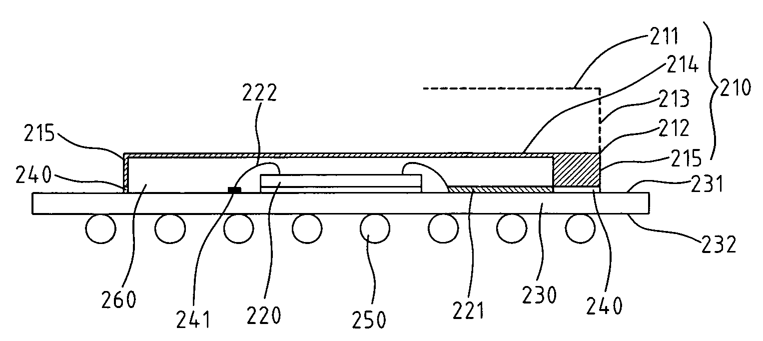
[0037]FIG. 3A shows a perspective view of the present invention. In this embodiment, the antenna with heat slug includes an antenna 311, an antenna feed metal sheet 312, at least a connection metal sheet 313, a heat slug 314, at least a chip 320, an antenna signal transmission line 321, a plurality of metal belts 340, a mold compound (described and shown in FIG. 3B) and a substrate 330. Antenna 311, antenna feed metal sheet 312, at least a connection metal sheet 313, heat slug 314 and support elements 315 constitute an antenna with heat slug module 310, which has a single metal sheet structure.

[0038]Substrate 330 has an upper surface 331 and a lower surface 332. Antenna signal transmission line 321 and a plurality of metal belts are formed on upper surface 331, where a chip 320 is attached. Chip 320 is connected to antenna signal transmission line 321 and bump pad 341 through metal wire 322. One end of connect metal sheet 313 is connected to antenna 311, and the other end is connect...

second embodiment

[0052]FIGS. 6A–6E show the fabricating process of the second embodiment according to the present invention.

[0053]The second embodiment has a fabricating process similar to that of the first embodiment. The difference is that the single metal sheet is cut or molded into a different shape in the process. First, as shown in FIG. 6A, at least a chip 520 is attached to upper surface 531 of substrate 530, on which antenna signal transmission line 521 and a plurality of metal belts 540 are already formed. Wire bond 522 is then formed to connect chip 320.

[0054]Then, a single metal sheet is cut or molded into a specific shape. As shown in FIGS. 6B and 6C, heat slug 514 can be either of the round shape or a rectangular shape, and antenna feed metal sheet 512 can be one of the support elements. In the following bending step, the single metal sheet is bended along dashed line 516, as shown in FIGS. 6B and 6C, to make heat slug 514 being perpendicular to support elements 515.

[0055]The next step ...

third embodiment

[0059]FIGS. 8A–8G show the fabricating process of the present invention.

[0060]First, at least a chip 720 is attached to upper surface 731 of substrate 730, on which antenna signal transmission line 721 and a plurality of metal belts 740 are already formed. Wire bond 722 is then formed to connect chip 320, as shown in FIG. 8A.

[0061]Then, the metal sheets are cut or molded into a specific shape, respectively. Because the structure of this embodiment uses double metal sheets, each of the metal sheets must be cut or molded into a different shape in accordance with the design. As the example shown in FIGS. 8B and 8C, antenna 711 has a rectangular or round shape, while antenna feed metal sheet 712 may have a triangular or rectangular shape. As for heat slug 714 and its plurality of support elements 715, the metal sheet can be cut or molded into a shape as shown in FIG. 1C.

[0062]The metal sheets are then bended so that heat slug 714 and support elements 715, and connection metal sheet 712 ...


PUM


Abstract

An apparatus of antenna with heat slug and its fabricating process are provided, in which the antenna with heat slug can be realized with a single sheet or double sheets of metal. Each single sheet of metal can be achieved by simply cutting and bending a metal plate. Thereby, it is a simple and low-cost fabricating process. In the known fabricating process of integrated circuit, the heat slug and the antenna can be combined in a module at the same step. Therefore, integrating the antenna with heat slug in a fabricating process needs not to develop a new process.

Description

FIELD OF THE INVENTION[0001]The present invention generally relates to an antenna and heat slug, and a method of forming the same, and more specifically to an apparatus and fabricating process of an antenna with heat slug to be used in a multi-chip module (MCM) package.BACKGROUND OF THE INVENTION[0002]The rapid development of integration modules has gained the increasing attention in a multi-chip-module package. Because a multi-chip-module includes multiple chips, the energy consumption is usually high in a single package, which leads to the need of integrating a heat slug in the package for heat dissipation to avoid the over-heating problem caused by the high energy consumption. Currently, the RF front-end module (RF FEM) has successfully integrated the balance / unbalance (balun) transformer, the power amplifier, the duplexer, the switch, the band-pass filter and the low noise amplifier (LNA) into a single package. Although the RF FEM is highly integrated, the antenna, being the fro...

Claims


Application Information

Patent Timeline
Patent Type & Authority Patents(United States)
IPC IPC(8): H01Q1/38H01L23/04H01L23/34H01L23/367H01L23/498H01L23/66H01Q9/04H01Q23/00
CPCH01L23/04H01L23/3675H01Q23/00H01Q9/0421H01Q9/0407H01L23/49816H01L23/66H01L25/0655H01L2224/48227H01L2224/32225H01L24/48H01L2224/45144H01L2924/3025H01L2924/16152H01L2223/6677H01L2224/48235H01L2224/73265H01L2924/01079H01L2924/15311H01L2924/00012H01L2924/00H01L2224/451H01L2924/00014H01L24/45H01L24/73H01L2924/14H01L2924/00015H01L2224/05599
Inventor TANG, CHIA-LUNYEH, SHIH-HUANG
Owner IND TECH RES INST
Why Eureka
Try Eureka