
Ureteral stent configured for improved patient comfort and aftercare

a ureteral stent and patient technology, applied in the field of stents, can solve the problems of stent migration and displacement, kidney dysfunction and eventual necrosis, swelling and inflammation of the upper urinary tract and the kidney, etc., to achieve less irritation, less rigidity, and ease pain and irritation.

Inactive Publication Date: 2006-05-16
BOSTON SCI SCIMED INC
View PDF30 Cites 112 Cited by
  • Summary
  • Abstract
  • Description
  • Claims
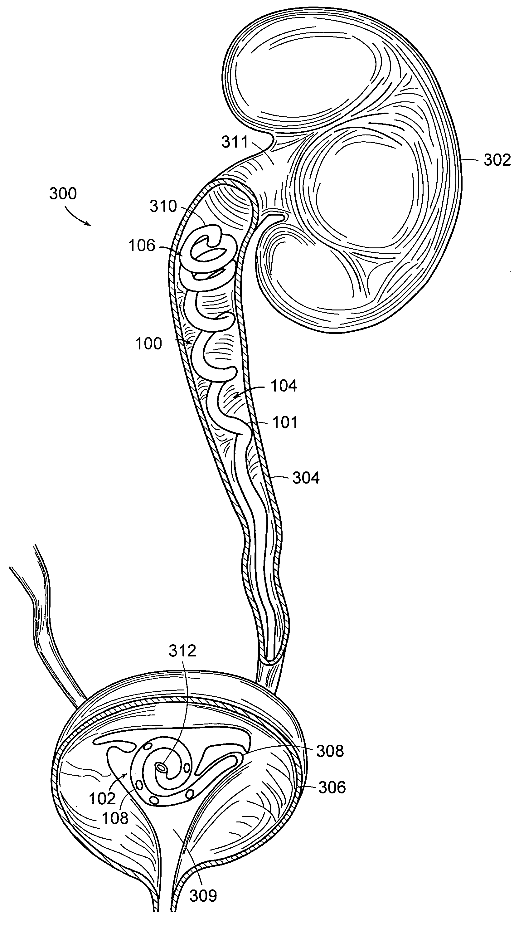
  • Application Information

AI Technical Summary

Benefits of technology

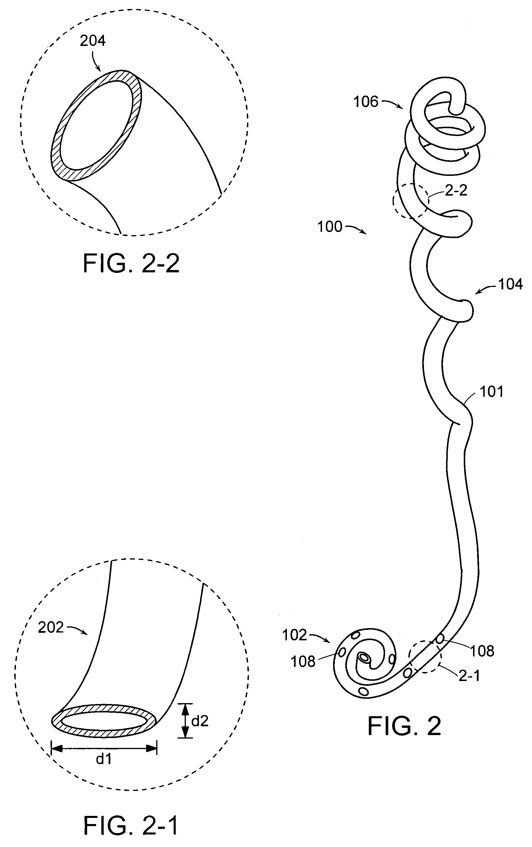
[0008]In one embodiment, the distal portion of the stent includes a section of hollow tube with a non-circular (e.g., somewhat flattened) profile. The non-circular profile is intended to more closely follow the contour of the intramural tunnel and ureteral vesical junction than does a circular profile. Extension or widening of the cross-section of the ureteral vesical junction due to the presence of the stent is minimized. Thus, there is less irritation caused by the stent at the ureteral vesical junction. The non-circular-profile section of the stent also provides a more flexible, less rigid distal end portion that eases pain and irritation, for example, in the trigonal region of the bladder.
[0009]The non-circular-profile section of the stent also provides for the reduction or elimination of urine reflux from the bladder to the kidney during voiding, thereby preventing the associated flank pain. Pressure external to the stent at the non-circular-profile section of the stent collapses the stent shut during voiding of the bladder and prevents reflux of urine to the kidney. After voiding, the stent opens again upon resumption of a normal bladder pressure. The non-circular-profile section of the stent may be made even more flexible and collapsible by the use of a thinner wall thickness in this section. In an embodiment, the distal portion of the stent is anchored in the bladder by a pigtail-shaped end portion, at least part of which has a non-circular cross-section to allow reduced irritation in the bladder and in the urinary vesical junction region.
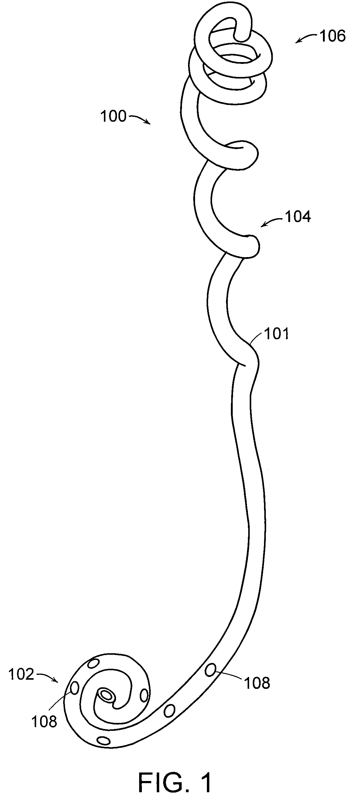
[0010]In another embodiment, the ureteral stent has a proximal portion configured to self-anchor inside an upper portion of the ureter, at or below the renal pelvis, to minimize or eliminate stent irritation in the kidney and / or the sensitive renal pelvis region. In one embodiment, a substantially three-dimensional helical coil shape of sufficiently large helix diameter provides an anchor inside the upper portion of the ureter. By anchoring the stent below the kidney, irritation is minimized in the sensitive renal pelvis region.
[0011]Another embodiment provides a stent with a portion forming an irregular helical coil shape to enable the stent to self-adjust with patient movement, thereby reducing irritation due to normal stretching and conformational change of the ureter. The irregular helical coil shape provides a self-adjusting reserve of stent length to allow for stent elongation, contraction, and other conformation change caused by movement of the ureter. The irregular helical coil shape may also provide an additional source of support for the stent within the ureter. In one embodiment, a stent has an irregular helical coil shape along its length, as well as a proximal end portion having a regular helical shape for anchoring the stent below the kidney. The portion of the stent having an irregular helical coil shape may be configured with sufficient helix diameter and height of helix extension so that (1) the proximal portion of the stent is more stably anchored below the kidney, and (2) the stent self-adjusts by elongating and contracting with patient movement. In one embodiment, the irregular helical coil shape has an increasing height of helix extension—fewer turns per unit length—toward the distal portion of the stent near the bladder. The irregular nature of the helical coil shape in this embodiment better follows the anatomy of the ureter than would a regular helical coil shape, and provides reduced stent weight, reduced pressure against ureteral tissue, and reduced irritation to the local tissue without compromising the self-anchoring ability of the stent. In an alternative embodiment, the stent has a portion forming a substantially regular helical coil shape to enable the stent to self-adjust with patient movement.

Problems solved by technology

Blockages of the ureter may cause hydronephrosis, a condition characterized by damming of urine in the kidneys, resulting in swelling and inflammation of the upper urinary tract and the kidneys.
This may lead to kidney dysfunction and eventual necrosis.
If the stent is not sufficiently anchored, this may result in stent migration and displacement.
Also, a stent may cause tissue irritation due to the relative movement between the stent and the ureter during natural stretching of the ureter, even when the stent is properly anchored.
A typical semi-rigid, anchored stent is unable to adjust for the natural extension and contraction of the ureter during bodily movements, resulting in pressure and irritation of the ureter and surrounding tissue.
Irritation may be caused by the static or dynamic contact of the semi-rigid stent with sensitive tissues of the body, such as the kidney and the renal pelvis.
Chronic trigonal tissue irritation may result from contact of tissue by the bladder-anchoring features of the stent, for example, pigtails at the stent ends.
Irritation problems are of concern regardless of the duration of use of the stent; however, irritation is of particular concern where use of a stent is required over a long period of time.
Another problem associated with ureteral stents is urine reflux and pain during urine voiding.
Because a typical ureteral stent holds the ureteral orifice open, increased bladder pressure during voiding is transmitted to the kidney through the stent, causing urine reflux and flank pain.

Method used


Image

  • Ureteral stent configured for improved patient comfort and aftercare
  • Ureteral stent configured for improved patient comfort and aftercare
  • Ureteral stent configured for improved patient comfort and aftercare

Examples


Embodiment Construction

[0017]The invention provides a ureteral stent configured for improved patient comfort and aftercare. In one embodiment, the stent has a distal portion with a somewhat flattened, non-circular cross-section, thereby providing a more flexible, less rigid, self-aligning lumen in the sensitive trigonal region of the bladder. In another embodiment, the stent features a proximal portion with a helical coil shape to allow self-anchoring of the stent below the kidney, at or below the renal pelvis. Furthermore, one embodiment includes a stent with a portion along its length having an irregular coil shape to allow self-adjustment of the stent with ureteral movement. Other embodiments of the invention include stents with various combinations of the aforementioned features.

[0018]Additionally, the invention provides a method of self-adjusting the effective length of a ureteral stent to compensate for patient movement, thereby providing improved patient comfort. An embodiment of the method include...


PUM


Abstract

A ureteral stent is configured for improved patient comfort and aftercare. The stent can have one or more of the following features: a distal portion with a somewhat flattened, non-circular cross-section that provides reduced irritation and elimination of urine reflux; a proximal portion with a helical coil shape that allows self-anchoring of the stent below the kidney; and a portion along the body of the stent having a coil shape that allows self-adjustment of the stent with ureteral movement.

Description

FIELD OF THE INVENTION[0001]The invention relates generally to stents; more particularly, the invention relates to ureteral stents.BACKGROUND OF THE INVENTION[0002]A ureter is a tubular passageway in the body that conveys urine from a kidney to a bladder. Blockages of the ureter may cause hydronephrosis, a condition characterized by damming of urine in the kidneys, resulting in swelling and inflammation of the upper urinary tract and the kidneys. This may lead to kidney dysfunction and eventual necrosis. Ureteral blockages, also called ureteral strictures, may be congenital or acquired. Acquired blockages may be caused by disease, injury, kidney stones, and tumors. Both congenital and acquired blockages generally require medical intervention, for example, the use of ureteral stents.[0003]Ureteral stents are used to facilitate urinary drainage from the kidney to the bladder in patients having a ureteral obstruction or injury, or to protect the integrity of the ureter in a variety of ...

Claims


Application Information

Patent Timeline
IPC IPC(8): A61F2/04A61M25/00
CPCA61M27/008A61B2017/00871A61M2210/1089A61F2002/048
Inventor LIU, CLIFFORD M.LI, JIANMIN E.
Owner BOSTON SCI SCIMED INC
Learn More