Dual pressure catalytic distillation hydrogenation column system for the front end of an ethylene plant

a hydrogenation column and catalytic distillation technology, which is applied in the direction of distillation, hydrocarbon distillation, organic chemistry, etc., can solve the problems of increasing the fouling rate in the bottom of the column, increasing the temperature of the catalyst bed, etc., to reduce the fouling rate, reduce the bottoms product temperature, and maximize the catalyst bed temperature in the system

Active Publication Date: 2006-05-16
CHEM RES & LICENSING CO
View PDF7 Cites 23 Cited by
  • Summary
  • Abstract
  • Description
  • Claims
  • Application Information

AI Technical Summary

Benefits of technology

[0005]The object of the invention is to provide and operate a front-end catalytic distillation hydrogenation system in an olefins plant to maximize the catalyst bed temperatures in the system while maintaining a low bottoms product temperature to reduce the fouling rate. The invention involves using two columns operating at different pressures. The catalytic reactor structures are in the first, high pressure column together with some fractionation zones. In the bottoms of the high pressure column, the temperature is regulated such that some lighter hydrocarbons remain. The bottoms from the high pressure column is sent to a second column which is a fractionator, operating at a lower pressure. The net bottoms product of this column is the net bottoms from the system. The temperature of this stream is low because total pressure of the column is low. The catalyst bed temperatures remain about the same as a single column, single pressure system but the bottoms temperatures in each of the columns is significantly lower. The net overhead of the low pressure column is totally condensed and sent back to the high pressure column.

Problems solved by technology

The conditions that achieve the optimum catalytic distillation catalyst temperature can, however, result in a column bottoms temperature that is relatively high and can increase the fouling rate in the bottom of the column.

Method used


Image

  • Dual pressure catalytic distillation hydrogenation column system for the front end of an ethylene plant
  • Dual pressure catalytic distillation hydrogenation column system for the front end of an ethylene plant
  • Dual pressure catalytic distillation hydrogenation column system for the front end of an ethylene plant

Examples


Embodiment Construction

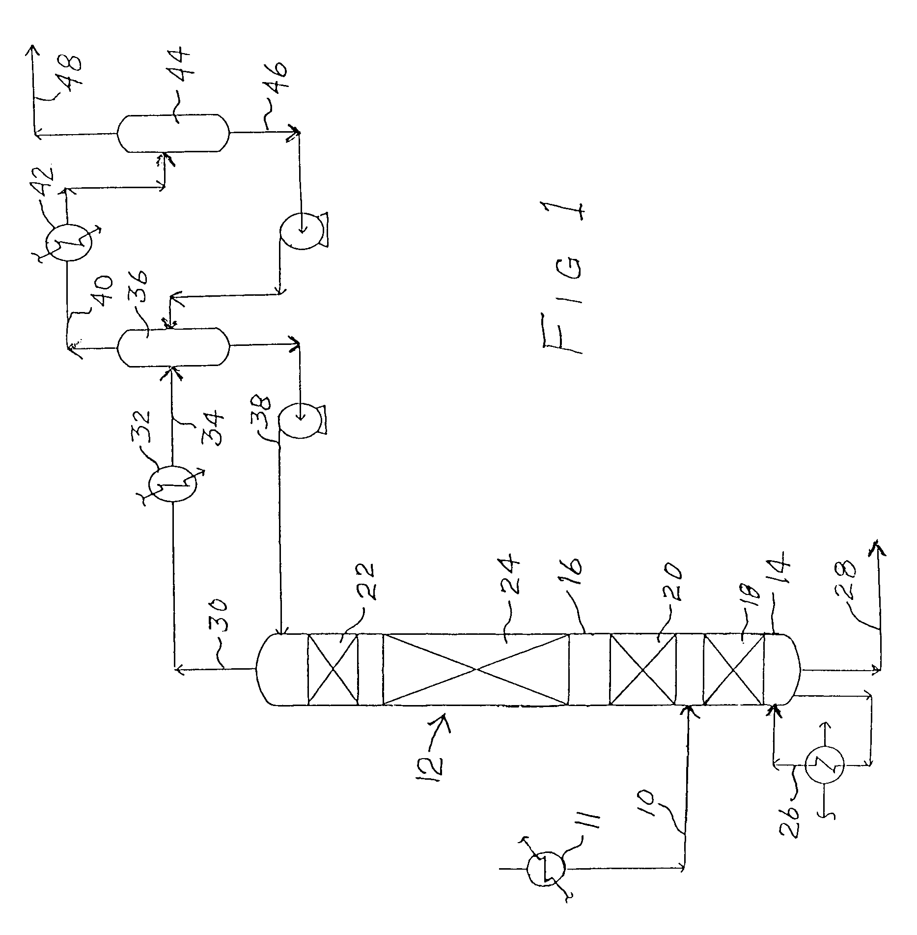
[0010]For a better understanding of the present invention, a prior art front-end catalytic distillation hydrogenation system as represented by FIG. 1 will be briefly described. As previously mentioned, such systems are disclosed and much more fully described in U.S. Pat. No. 5,679,241 and U.S. patent application Ser. No. 10 / 202,702. The objective of these systems is to remove a significant fraction of the hydrogen by hydrogenating the C2 to C5 diolefins and acetylenes without significant hydrogenation of the ethylene and propylene. In this system, the compressed charge gas 10, which may be heated at 11, is fed to the catalytic distillation hydrogenation column 12 which simultaneously carries out a catalytic reaction and distillation. The column 12 has a stripping section 14 below the feed 10 and a rectifying / reaction section 16 above the feed. Both of the sections contain distillation internals forming separation zones 18, 20 and 22 while the rectifying / reaction section 16 contains ...


PUM

PropertyMeasurementUnit
temperatureaaaaaaaaaa

Abstract

The charge gas from the thermal cracking of a hydrocarbon feedstock is processed in a front-end catalytic distillation hydrogenation system of an olefins plant to more effectively recover ethylene and propylene product and to process the by-products. The rate of fouling in the system is reduced by employing two columns in the system with the first column operating at a higher pressure and the second column operating at a lower pressure. The hydrogenation as well as fractionation takes place in the first column while the second column is only a fractionator. The temperature of the bottoms from each column is maintained at a temperature less than 200° C. to avoid fouling.

Description

BACKGROUND OF THE INVENTION[0001]The present invention relates to a process and system for the production of olefins and particularly to processing the charge gas feed to more effectively recover the product and process the by-products.[0002]Ethylene, propylene and other valuable petrochemicals are produced by the thermal cracking of a variety of hydrocarbon feedstocks ranging from ethane to vacuum gas oils. In the thermal cracking of these feedstocks, a wide variety of products are produced ranging from hydrogen to pyrolysis fuel oil. The effluent from the cracking step, commonly called charge gas or cracked gas, is made up of this full range of materials which must then be separated (fractionated) into various product and by-product streams followed by reaction (hydrogenation) of at least some of the unsaturated by-products.[0003]The typical charge gas stream, in addition to the desired products of ethylene and propylene, contains C2 acetylenes, C3 acetylenes and dienes and C4 and...

Claims


Application Information

Patent Timeline
Patent Type & Authority Patents(United States)
IPC IPC(8): C07C5/00C07C7/04C07C7/163
CPCC07C7/04C07C7/163C07C11/04C07C11/06Y10S203/06Y02P20/10C10G7/00C10G51/02
Inventor SUMNER, CHARLESHEINEMAN, JEFFREY L.DI BIASE, CHRISTOPHER A.
Owner CHEM RES & LICENSING CO
Why Eureka
Try Eureka