
Data processing system providing hardware acceleration of input/output (I/O) communication

a data processing system and hardware acceleration technology, applied in the field of data processing, can solve the problems of further latency, etc., and achieves the effect of consuming bandwidth, reducing operating system performance, and adding latency to each i/o data transfer

Active Publication Date: 2006-05-16
IBM CORP
View PDF4 Cites 42 Cited by
  • Summary
  • Abstract
  • Description
  • Claims
  • Application Information

AI Technical Summary

Benefits of technology

The present invention aims to improve the efficiency of data processing systems by addressing the shortcomings of conventional input / output communication. It provides a solution by integrating a processor core, interconnect interface, and external communication adapter to support input / output communication. The invention also includes a bypass mechanism to improve performance by bypassing unnecessary instructions and optimizing data processing. Overall, the invention enhances data processing performance and efficiency by optimizing input / output communication and reducing latency and bandwidth consumption.

Problems solved by technology

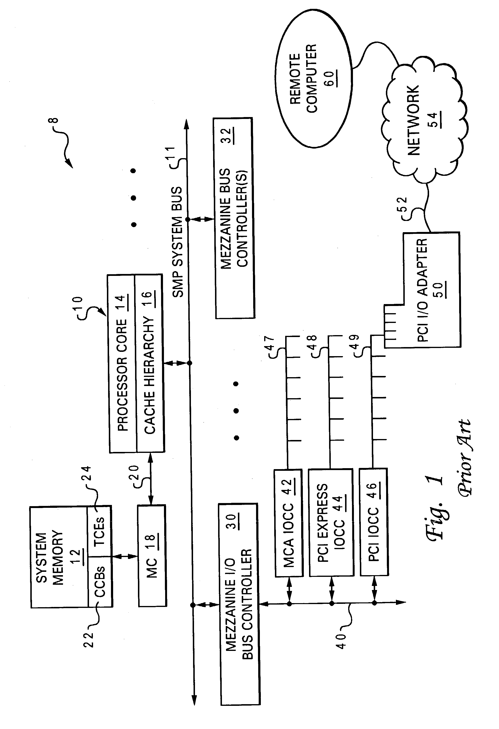
The overhead associated with the creation and management of TCE tables in system memory decreases operating system performance, and the translation of I / O addresses by the IOCC adds latency to each I / O data transfer.
Further latency is incurred by the use of locks to synchronize access by multiple processes to the I / O adapter and system memory, as well as by arbitrating for access to, and converting between the protocols implemented by the I / O (e.g., PCI) bus, the mezzanine bus, and SMP system bus.
Moreover, the transmission of I / O data transfers over the SMP system bus consumes bandwidth that could otherwise be utilized for possibly performance critical communication (e.g., of read requests and synchronizing operations) between processing units.
The use of interrupts to facilitate communication between I / O adapters and calling processes is inefficient because it requires two context switches for each data transfer and consumes processor cycles executing interrupt handler(s) rather than performing useful work.

Method used


Image

  • Data processing system providing hardware acceleration of input/output (I/O) communication
  • Data processing system providing hardware acceleration of input/output (I/O) communication
  • Data processing system providing hardware acceleration of input/output (I/O) communication

Examples


Embodiment Construction

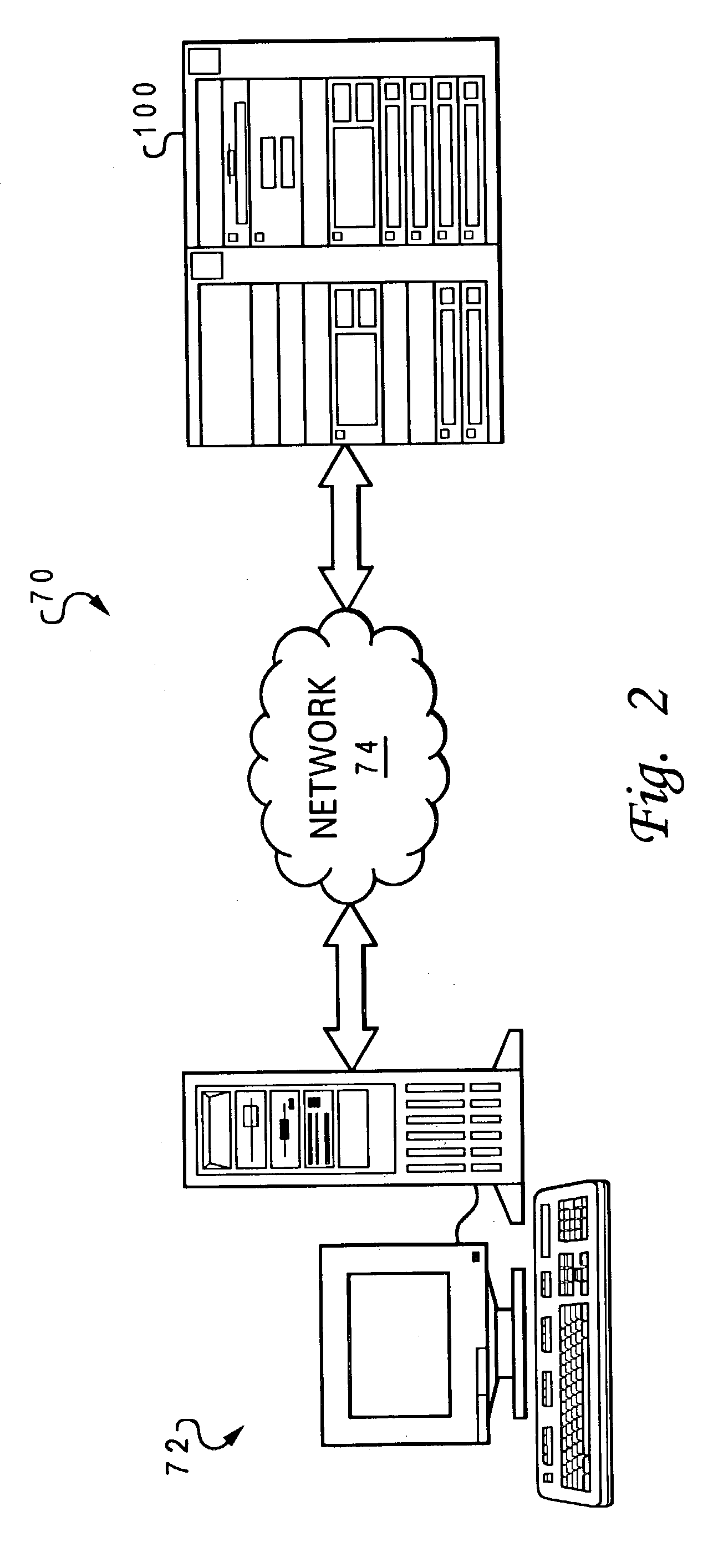
[0036]With reference again to the figures and in particular with reference to FIG. 2, there is illustrated an exemplary network system 70 in which the present invention may advantageously be utilized. As illustrated, network system 70 includes at least two computer systems (i.e., workstation computer system 72 and server computer system 100) coupled for data communication by a network 74. Network 74 may comprise one or more wired, wireless, or optical Local Area Networks (e.g., a corporate intranet) or Wide Area Networks (e.g., the Internet) that employ any number of communication protocols. Further, network 74 may include either or both packet-switched and circuit-switched subnetworks. As discussed in detail below, in accordance with the present invention, data may be transferred by or between workstation 72 and server 100 via network 74 utilizing innovative methods, systems, and apparatus for input / output (I / O) data communication.

[0037]Referring now to FIG. 3, there is depicted an...


PUM


Abstract

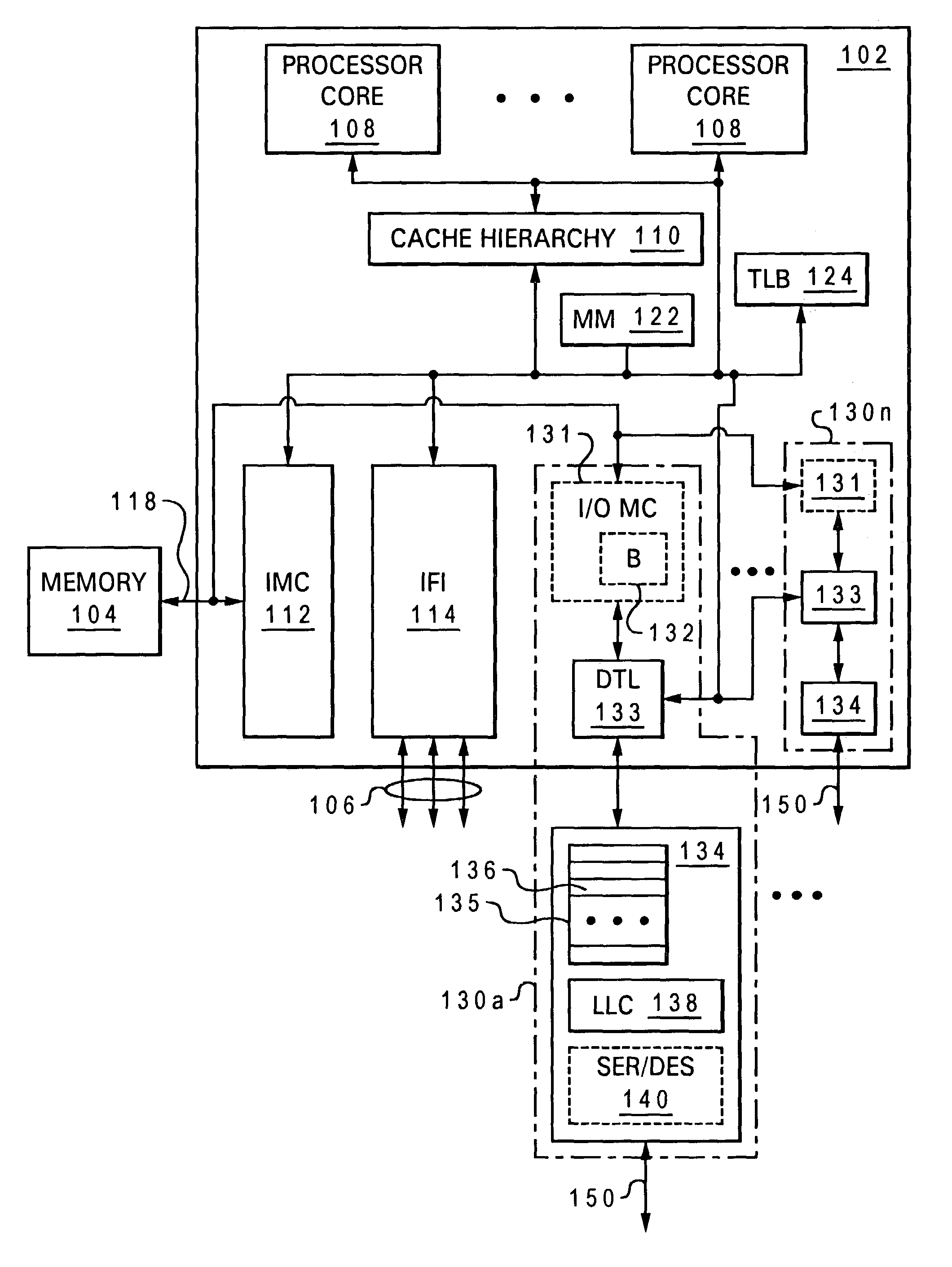
An integrated circuit, such as a processing unit, includes a substrate and integrated circuitry formed in the substrate. The integrated circuitry includes a processor core that executes instructions, an interconnect interface, coupled to the processor core, that supports communication between the processor core and a system interconnect external to the integrated circuit, and at least a portion of an external communication adapter, coupled to the processor core, that supports input / output communication via an input / output communication link.

Description

BACKGROUND OF THE INVENTION[0001]1. Technical Field[0002]The present invention relates in general to data processing and, in at least one aspect, to input / output (I / O) communication by a data processing system.[0003]2. Description of the Related Art[0004]In a conventional data processing system, input / output (I / O) communication is typically facilitated by a memory-mapped I / O adapter that is coupled to the processing unit(s) of the data processing system by one or more internal buses. For example, FIG. 1 illustrates a prior art Symmetric Multiprocessor (SMP) data processing system 8 including a Peripheral Component Interconnect (PCI) I / O adapter 50 that supports I / O communication with a remote computer 60 via an Ethernet communication link 52.[0005]As illustrated, prior art SMP data processing system 8 includes multiple processing units 10 coupled for communication by an SMP system bus 11. SMP system bus may include, for example, an 8-byte wide address bus and a 16-byte wide data bus...

Claims


Application Information

Patent Timeline
Patent Type & Authority Patents(United States)
IPC IPC(8): G06F3/00G06F12/08G06F12/02G06F12/10G06F13/12G06F13/14
CPCG06F13/124G06F12/0835
Inventor ARIMILLI, RAVI KUMARCARGNONI, ROBERT ALANGUTHRIE, GUY LYNNSTARKE, WILLIAM JOHN
Owner IBM CORP
Learn More