Pump as a pressure source for supercritical fluid chromatography

a pressure source and fluid chromatography technology, applied in the direction of positive displacement liquid engine, separation process, instruments, etc., can solve the problems of chromatographic behavior, inability to distinguish from true supercritical operation, and compensation too small to deal with fluids most often used in sfc, so as to reduce oscillation, dampen damaging effects, and increase the volumetric capacity of sfc

Inactive Publication Date: 2006-05-23
WATERS TECH CORP
View PDF13 Cites 12 Cited by
  • Summary
  • Abstract
  • Description
  • Claims
  • Application Information

AI Technical Summary

Benefits of technology

[0017]The exemplary embodiment is useful in a high-pressure chromatography system, such as a supercritical fluid chromatography (SFC) system, for using a pump as a pressure source for precision pumping of a compressible fluid. The preferred exemplary embodiment comprises a pressure regulation assembly installed downstream from a compressible fluid pump but prior to combining the compressible flow with a relatively incompressible modifier flow stream that allows the replacement of an high-grade SFC pump in the compressible fluid flow stream with an inexpensive and imprecise pump. The imprecise pump becomes capable of moving the compressible fluid flow stream in a precise flow rate and pattern. The assembly dampens the damaging effects of an imprecise pump, such as large pressure oscillations caused by flow ripples and noisy pressure signals that do not meet precise SFC pumping requirements.
[0018]The invention regulates the outlet pressure from a pump using a system of pressure regulators and a restriction in the flow stream. To regulate outlet pressure directly downstream of a pump, a forward-pressure regulator (FPR) is installed in the flow line. Downstream of the forward-pressure regulator the flow is restricted with a precision orifice. The orifice can be any precision orifice, such as a jewel having a laser-drilled hole or precision tubing. Downstream of the orifice is a back-pressure regulator (BPR). The series of an FPR-orifice-BPR is designed to control the pressure drop across the orifice, which dampens out oscillation from noisy pressure signals caused by large ripples in the flow leaving the pump. An additional embodiment uses a differential pressure transducer around the orifice with a servo control system to further regulate the change in pressure across the orifice. The combination allows the replacement of an expensive, SFC-grade pump having compressibility compensation with an inexpensive, imprecise pump such as an air-driven pump.
[0019]The system can be multiplexed in parallel flow streams, thereby creating significantly greater volumetric capacity in SFC and a greater number of inexpensive compressible fluid flow channels. The parallel streams can all draw from a single source of compressible fluid, thereby reducing the costs of additional pumps. Some alternatives to the multiplexed system uses the single compressible fluid pump to raise pressure in the flow line from the compressible fluid source combined with additional second stage booster pumps in each individual SFC flow stream. Another system replaces multiple modifier solvent pumps for each channel with a single, multi-piston pump having outlets for each individual channel.

Problems solved by technology

In this lower region, especially when organic modifiers are used, chromatographic behavior remains superior to traditional HPLC and often cannot be distinguished from true supercritical operation.
Not any reciprocating pump can be used with a pump head chiller to make an SFC pump.
While most HPLC pumps can be set to compensate for the compressibility, compensation is too small to deal with the fluids most often used in SFC.
Inadequate compensation results in errors in both the flow rate and the composition of modified fluids.
Without correct compressibility compensation, the pump either under- or over-compresses the fluid causing characteristic ripples in flow and pressure.
The result is noisy baselines and irreproducibility.
Pumping compressible fluids, such as CO2, at high pressures in SFC systems while accurately controlling the flow, is much more difficult than that for a liquid chromatography system.
SFC systems use two pumps to deliver fluids to the mobile phase flow stream, and each pump usually adds pressure and flow ripples and variances that cause baseline noise.
The two pumps also operate at different frequencies, different flow rates, and require separate compressibility compensations, further adding to the complexity of flow operations.
The prior art methods require control of the fluid temperature and are somewhat limited since they does not completely compensate for the compressibility.
The co-existence of several phases destroys chromatographic separations and efficiency.
Since the peak areas are representative for the concentration of the chromatographically separated sample substance, fluctuations in the flow rate would impair the accuracy and the reproducibility of quantitative measurements.
At high pressures, compressibility of solvents is very noticeable and failure to account for compressibility causes technical errors in analyses and separation in SFC.
A pressure control pump with a fixed restrictor results in broadened peaks and higher background noise through a packed column.
The linear velocity increases excessively during a run, thereby degrading the chromatography.
The assembly dampens the damaging effects of an imprecise pump, such as large pressure oscillations caused by flow ripples and noisy pressure signals that do not meet precise SFC pumping requirements.

Method used


Image

  • Pump as a pressure source for supercritical fluid chromatography
  • Pump as a pressure source for supercritical fluid chromatography
  • Pump as a pressure source for supercritical fluid chromatography

Examples


Embodiment Construction

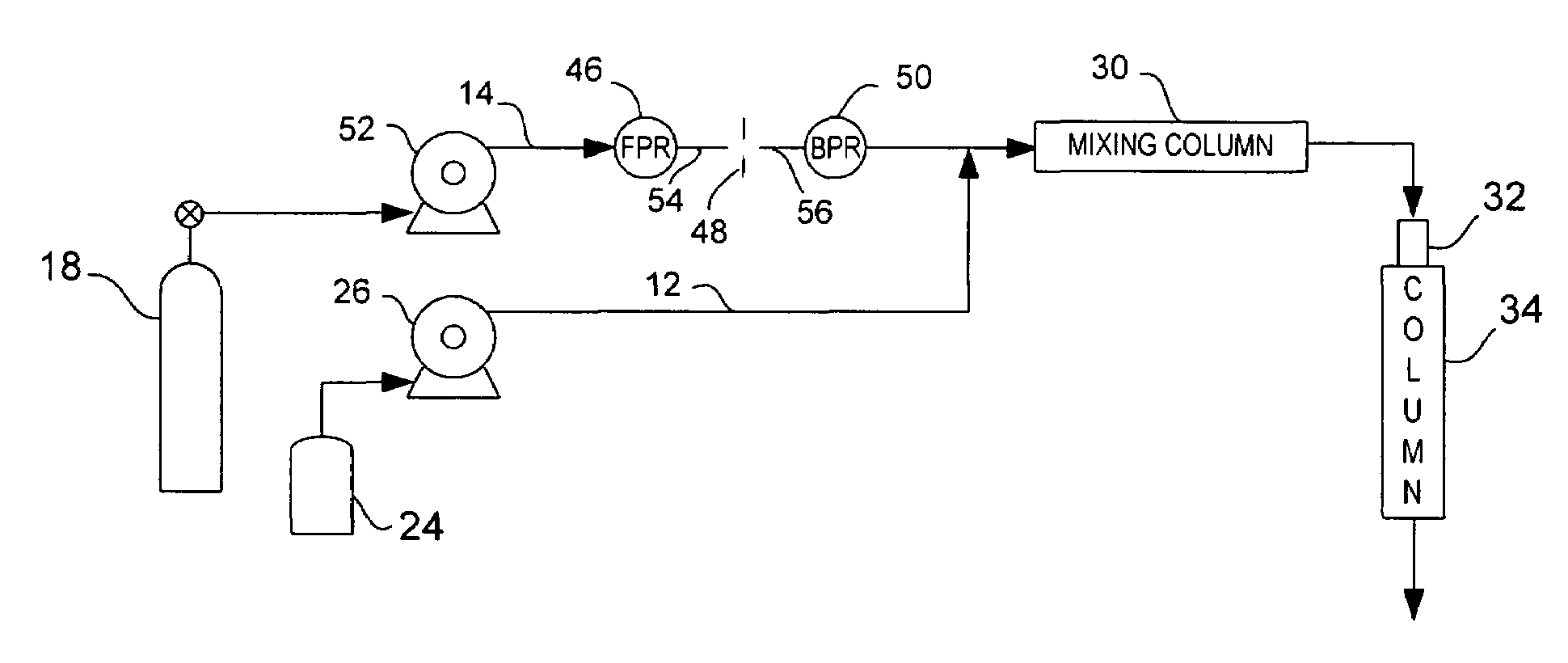
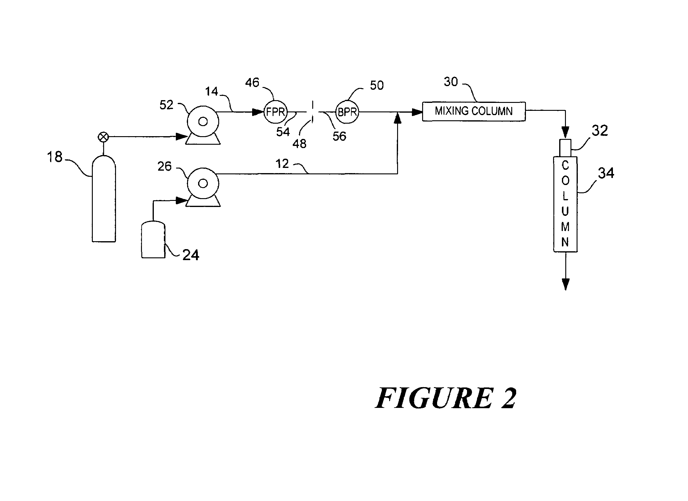
[0027]There is described herein a preferred embodiment of the present invention for a device and method in a high-pressure chromatography system, such as supercritical fluid chromatography (SFC), that uses a pump as a pressure source for precision pumping of a compressible fluid. As further described herein, the preferred exemplary embodiment comprises a pressure regulation assembly installed downstream from a compressible fluid pump but prior to combining the compressible flow with a relatively incompressible flow stream. The present invention provides for the replacement of an expensive SFC-grade pump for compressible fluids having dynamic compressibility compensation, with a less-expensive and imprecise pump to move a compressible fluid flow stream in a precise flow rate and pressure signal. The assembly dampens the damaging effects of a low-grade pump, such as large pressure and flow oscillations caused by flow ripples and noisy pressure signals that do not meet precise SFC pump...


PUM


Abstract

The invention is a device and method in a high-pressure chromatography system, such as a supercritical fluid chromatography (SFC) system, that uses a pump as a pressure source for precision pumping of a compressible fluid. The preferred exemplary embodiment comprises a pressure regulation assembly installed downstream from a compressible fluid pump but prior to combining the compressible flow with a relatively incompressible modifier flow stream. The present invention allows the replacement of an high-grade SFC pump in the compressible fluid flow stream with an inexpensive and imprecise pump. The imprecise pump becomes capable of moving the compressible fluid flow stream in a precise flow rate and pattern. The assembly dampens the damaging effects of an imprecise pump, such as large pressure oscillations caused by flow ripples and noisy pressure signals that do not meet precise SFC pumping requirements.

Description

[0001]This is a Division of application Ser. No. 10 / 117,984, filed Apr. 05, 2002, now U.S. Pat. No. 6,648,609. The invention relates to a device and method for using a pump as a pressure source, instead of a flow source, in a high-pressure chromatography system, such as supercritical fluid chromatography.FIELD OF THE INVENTION[0002]The invention relates to a device and method for using a pump as a pressure source, instead of a flow source, in a high-pressure chromatography system, such as supercritical fluid chromatography.BACKGROUND OF THE INVENTION[0003]An alternative separation technology called supercritical fluid chromatography (SFC) has advanced over the past decade. SFC uses highly compressible mobile phases, which typically employ carbon dioxide (CO2) as a principle component. In addition to CO2, the mobile phase frequently contains an organic solvent modifier, which adjusts the polarity of the mobile phase for optimum chromatographic performance. Since different components ...

Claims


Application Information

Patent Timeline
Patent Type & Authority Patents(United States)
IPC IPC(8): F04B49/03F04B11/00F04B49/22
CPCF04B49/225F04B11/0091Y10T137/88054Y10T137/87917Y10T137/7838G01N2030/326B01D15/40
Inventor BERGER, TERRY A.FOGELMAN, KIMBER D.KLEIN, KENNETHSTAATS, III, L. THOMPSONNICKERSON, MARKBENTE, III, PAUL F.
Owner WATERS TECH CORP
Why Eureka
Try Eureka