
Apparatus for fishing telecommunication or electrical wires, optical cables or conduit behind walls

a technology for optical cables and cables, applied in the direction of cables, special-purpose vessels, cables laying apparatus, etc., can solve the problems of wasting time, energy and expense, affecting the operation of the apparatus, and reducing the service life of the apparatus, etc., to achieve reliable operation, easy to use, and cost-effective

Inactive Publication Date: 2006-05-30
HEWITT TODD R
View PDF16 Cites 19 Cited by
  • Summary
  • Abstract
  • Description
  • Claims
  • Application Information

AI Technical Summary

Benefits of technology

[0016]The present invention provides a cost effective method and means for fishing telecommunication or electrical wiring within an unobstructed single bay containing joists behind a sheetrock or plaster wall, without having to drill multiple holes or cut several slots for the string-up operation. Apparatus of the invention is easy to use and reliable in operation. As such, it is especially well suited for use by building contractors as well as owners of residential dwellings.
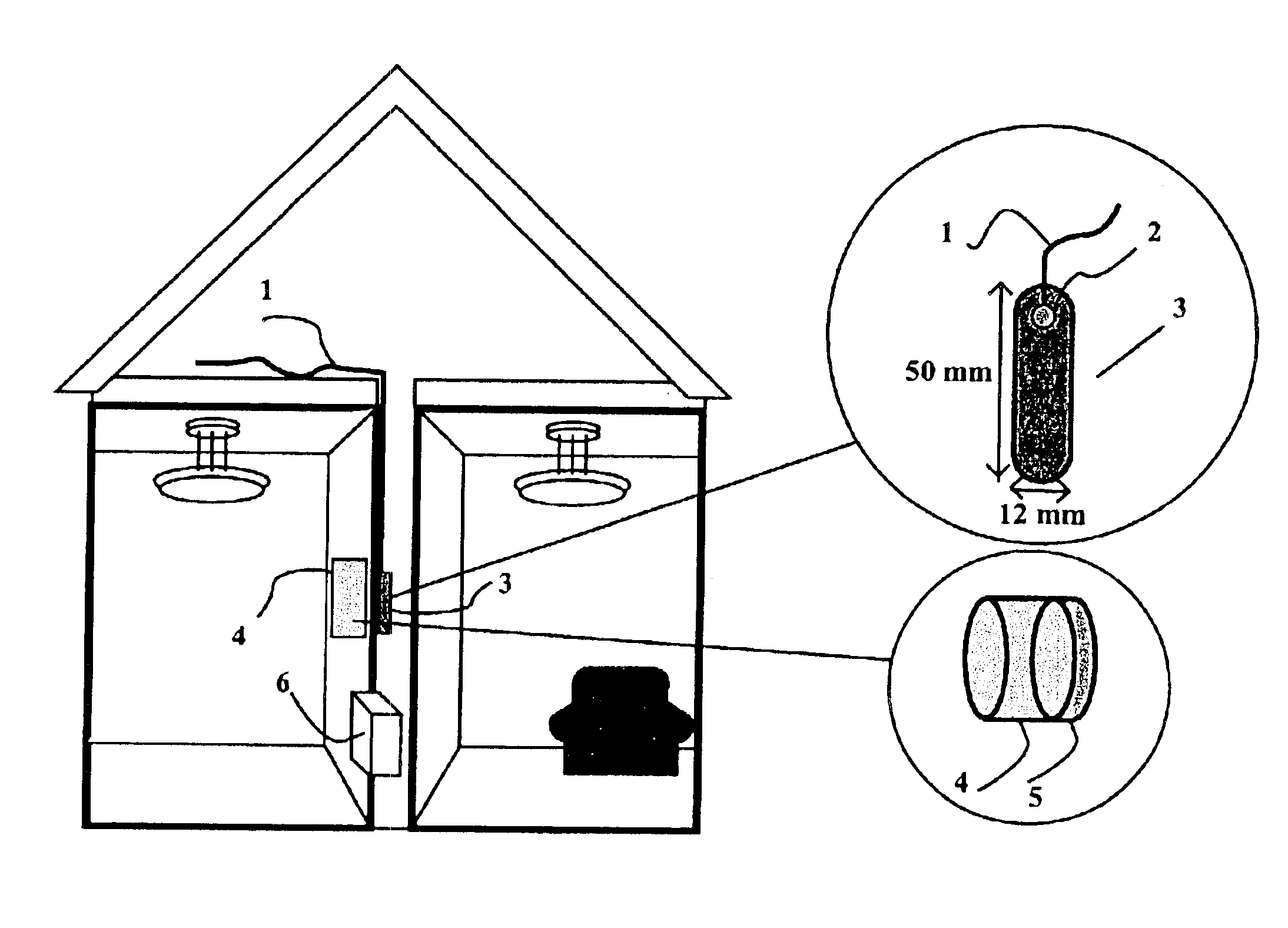
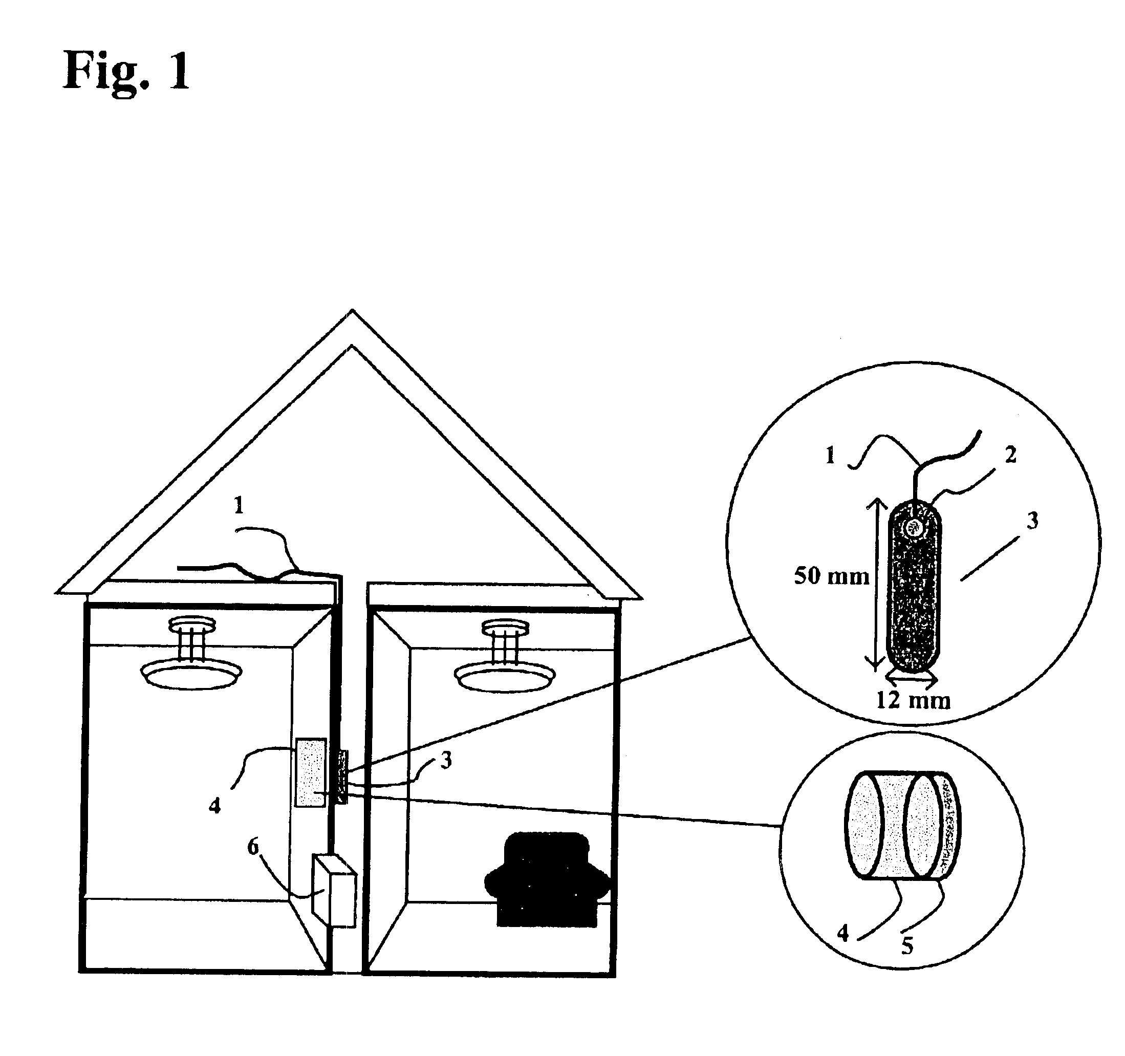
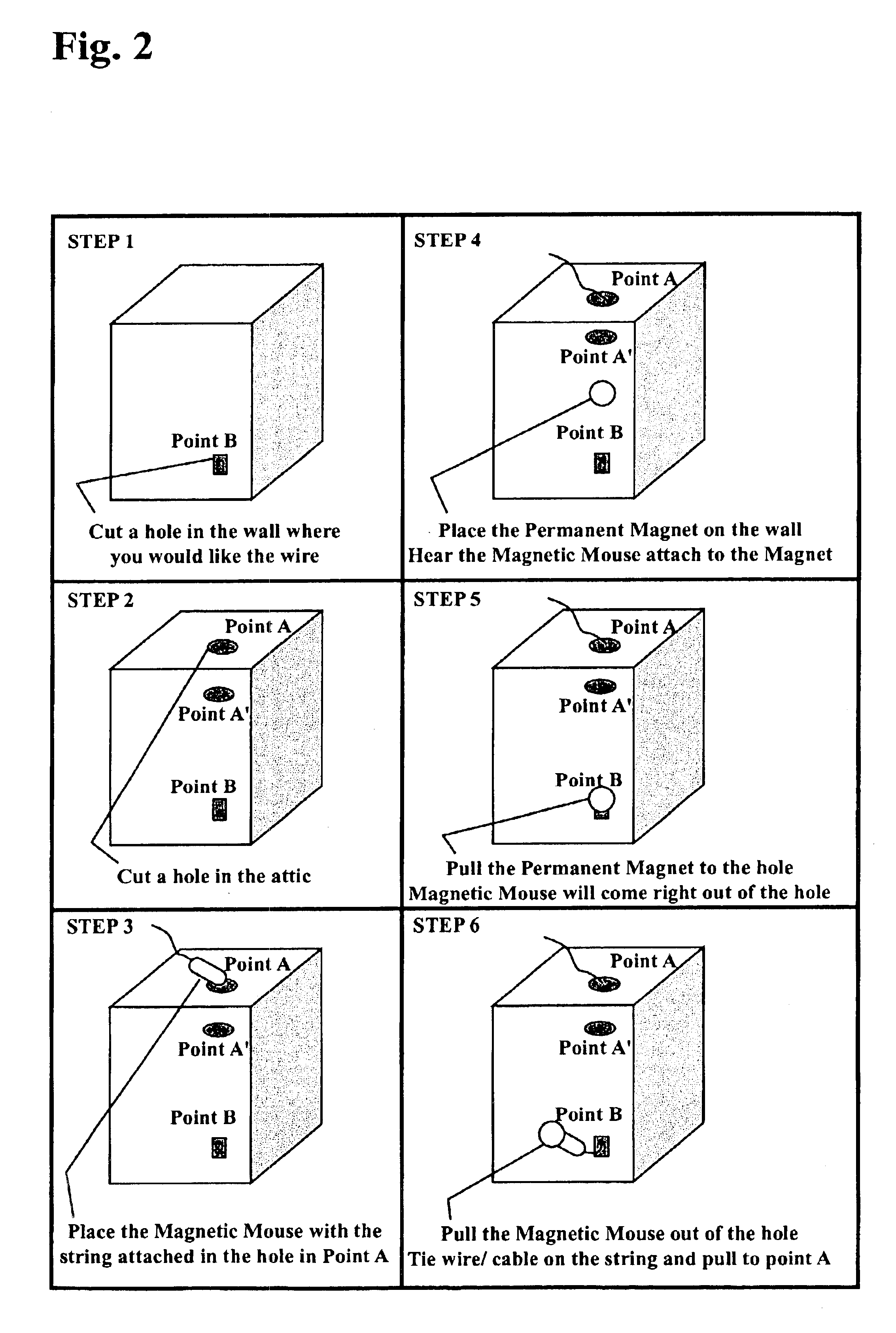
[0017]Generally stated, there is provided an apparatus for fishing telecommunication and electrical wires and optical cables behind plaster or sheetrock walls. The apparatus has three elements, comprising: (i) a magnetic mouse made from a soft magnetic sheet approximately 3 mm thick and approximately 50 mm long×12 mm wide, which travels behind the sheetrock or plaster wall in a single bay attached to a string; (ii) a high energy product permanent magnet adapted for movement on the interior wall, which drives the magnetic mouse behind the sheetrock or plaster wall within the single bay, to thereby maintain strong attraction with the magnet; and (iii) a string attached to the magnetic mouse, creating a connection line between point A to point B, so that a wire, cable or conduit attached to the string can be pulled up through the fished line to complete the electrical, optical or conduit pathway between points A and B. A low friction coating such as a Teflon™ coating is applied to the magnetic mouse. The low friction coating allows the magnetic mouse to follow the movement of the magnet easily, due to reduced frictional forces. In another embodiment, the magnetic mouse 3 is coated with paint to prevent it from rusting. Generally, the permanent magnet is of the NdFeB type, which is a high-energy product magnet, having an energy product over 40 mega-gauss oerstead and is not subject to self-demagnetization. It has a strong magnetic attractive force and attracts the magnetic mouse in the 6 to 16 mm range effectively and is capable of driving the magnetic mouse behind the wall as the permanent magnet is moved on the interior surface of the wall. The permanent magnet is covered with a felt pad to prevent damage to the finish of the walls by scratching as the permanent magnet is moved from point A to point B. Preferably, the string is fabricated from natural or synthetic materials; or flexible mono-filament yarn; or multi-filament twisted flexible fine wire.

Problems solved by technology

Those responsible for construction and maintenance of homes and commercial buildings have long struggled to devise a method and means for addressing the difficult task of bringing in new wires for electrical service.
This string-up process is wasteful, consuming time, energy and expense.
If excessive force is used during pulling of the string, or if the electrical wire offers excessive resistance, the magnet may let go, breaking the guided pull.
Operational reliability thus presupposes lack of resistance of the wire to the pulling process, which is oftentimes not present during all installation conditions.
These additional elements increase the cost and decrease reliability of the Shanahan device.
In addition, the electromagnet is generally weak, especially at increased distance between the electromagnet and the magnetizable body, and consumes battery power resulting in reduced battery service life.
Accordingly, the tape-carrying roller tends to lose contact with the inner wall and wander, resulting in unreliable string-up attempts.
It does not assist with pushing electrical wire behind a sheetrock wall, when no conduit is present.
Since the electromagnet used in the first embodiment is heavy and carried by a flexible string, it can swing and may not easily contact the inserted fish tape at the lower hole, especially if the upper and lower holes are not aligned in a vertical plane.
It may not be inserted vertically, thereby impairing its ability to contact the inserted magnetizable fish tape at the upper hole.
Such sustained contact is oftentimes not readily accomplished, and requires a high current that is not easily provided by a battery power source.
The device is designed to drill holes in inaccessible cross members, which essentially obstruct the ability to pass a conduit or wire through the wall behind the sheetrock.
This actively clears the way for inserting a wire or conduit through behind a sheetrock or plaster wall, but does not provide the functionality of stringing up a telecommunication or electrical wire.
Such drilling and cutting operations mar the appearance of the wall and require a refinishing operations wherein plaster is reapplied to regain an appropriate wall substrate appearance and the wall is thereafter repainted or wall papered.
Such refinishing operations are time consuming and expensive.

Method used


Image

  • Apparatus for fishing telecommunication or electrical wires, optical cables or conduit behind walls
  • Apparatus for fishing telecommunication or electrical wires, optical cables or conduit behind walls
  • Apparatus for fishing telecommunication or electrical wires, optical cables or conduit behind walls

Examples


Embodiment Construction

[0022]Adding additional wiring within pre-existing buildings is frequently necessary. Such additional wiring is generally required to create new outlets in a room, or to install telecommunication lines such as high-speed Internet connections or optical network connections. During installation of such wiring it is necessary to create pathways behind pre-existing walls. Installation of these connections usually requires drilling holes or cutting slots within the sheetrock or plaster walls or ceilings in order to string the wiring. It is often more difficult to run connections through a ceiling since gravity does not assist following a given track. Consequently, devices previously employed by prior art workers have heretofore been unable to successfully string-up a connection without drilling a plurality of cutting holes through the ceiling.

[0023]The present invention provides a low cost reliable apparatus comprising a magnetic mouse comprising a soft magnetic body, typically steel, co...


PUM


Abstract

An apparatus fish's telecommunication or electrical wiring, optical cables or conduit behind walls without need for a plurality of drilled holes or cutting slots. The apparatus has a central drive shaft comprising a magnetic mouse; a string; and a permanent magnet. The magnetic mouse comprises a sheet cut from a soft magnetic sheet material, coated with a low friction surface finish. It is attached to the string and dropped through a first hole location in the wall into a common bay between joists behind the wall. Following insertion, the magnetic mouse is driven from the first hole location to a second hole location by a permanent magnet, which is translated over the ceiling or interior of the wall. Translation of the permanent magnet moves the magnetic mouse inside the ceiling or wall, carrying the string through the common bay from said second hole location to said first hole location, thereby establishing a fishing line. The permanent magnet is, optionally, covered with felt to prevent scratching of the wall. A telecommunication or electrical wire; or optical cable; or conduit is attached to said fishing line, causing it to be pulled through the common bay from said second hole location to said first hole location.

Description

BACKGROUND OF THE INVENTION[0001]1. Field of the Invention[0002]The present invention relates to installation of conduit within confined spaces behind walls of commercial or residential buildings; and more particularly to a method and means for stringing up new or additional telecommunication wires, optical cables or electrical wiring behind sheetrock or plaster walls in existing homes or office buildings, without having to open out or cut pathways for the wire.[0003]2. Description of the Prior Art[0004]Those responsible for construction and maintenance of homes and commercial buildings have long struggled to devise a method and means for addressing the difficult task of bringing in new wires for electrical service. They are also tasked with the charter of providing high-speed Internet capability using telecommunication wires or optical cables without having to tear up existing walls and ceilings. Generally, installation includes tearing up of progressive slots or holes in the ceili...

Claims


Application Information

Patent Timeline
IPC IPC(8): E21C29/16H02G3/00
CPCH02G3/00
Inventor HEWITT, TODD R.
Owner HEWITT TODD R
Learn More