Vacuum-assisted pad conditioning system and method utilizing an apertured conditioning disk

a technology of vacuum-assisted pads and conditioning disks, which is applied in the field of vacuum-assisted pads conditioning systems and methods utilizing apertured conditioning disks, can solve the problems of undesirably slow and inefficient conditioning, the actual conditioning pressure is further uncertain, and the mechanism producing vertical movement is limited in the force range, so as to reduce the amount of upw, and control the flatness of the abrasiv

Inactive Publication Date: 2006-05-30
TBW IND INC
View PDF15 Cites 15 Cited by
  • Summary
  • Abstract
  • Description
  • Claims
  • Application Information

AI Technical Summary

Benefits of technology

[0033]The pad conditioning system used in the present invention, as set forth in U.S. Pat. No. 6,508,697 referred to above, utilizes abrasive disks that have an open structure to collect debris or swarf as it is being abraded off of the substrate surface. The system has a pad conditioning apparatus, process fluids, a vacuum capability to pull waste material out of the conditioning pad, self-contained flushing means, and a piezo-electric device for vibrating the pad conditioning abrasive. The debris, as it is being created, is pulled through the holes of the abrasive and magnetic support, into a chamber behind the support, and into a conduit to a disposal system. Jets of water, other cleaning or neutralizing chemicals are sprayed through the abrasive in conjunction with the waste removal. This flushing / abrading / vacuum cleaning thoroughly cleans the polishing pad surface, enabling alternative materials to be introduced without cross contamination. All of these elements combine in operation to provide a unique and effective system for conditioning and cleaning polishing pads. They also allow for the introduction into the conditioning, cleaning and polishing processes operation-specific slurries or other chamicals, without the need for extensive retooling, platen change-out, and additional material handling.
[0036]A series of pressurized water holes radiating out from the center of the impeller disk allows frill coverage of the abrasive disk and aids in the break up of the static layers in the pores of the polishing pad. The vacuum action pulls the water and debris immediately up through the aligned holes, or “open structure”, in tie stacked disks allows collection of debris or swarf, as it is being dislodged from the surface of the pad, allowing continuous conditioning and cleaning without interference of the debris between the abrasive disk and the surface of the wafer. The magnetic fastening structure allows for rapid changeover and provides controlled flatness for the abrasive. A mechanical method can also he used which would be gimbaled for alignment and cushioning. One exemplary mechanical method of providing this gimbaling comprises a ball and socket design that will function to level the abrasive disk within the conditioning holder. Barbed fitting may he used with the ball and socket arrangement to provide a means for coupling a pressurized medium into the conditioning holder. The use of a gimbaled arrangement allows for the various force elements involved in the conditioning process (an axial downforce of the conditioning head on the pad surface, a vacuum force drawing debris from the pad, and perhaps a push of conditioning fluids onto the pad surface at a pressure of, for example, 100 psi). Independently controlling the movement of the conditioning head / apertured disk with respect to the outer chamber allows for the arrangement to respond to sheer (normal) force, without the use of a relatively high conformal force. By eliminating any dependence between the two, a “zero” downforce can be imparted (that is, a lifting of the conditioning head) while allowing the outer chamber (and associated vacuum) to remain in contact with the pad surface. Vacuum pulls the wastes from the process, and lifts the polishing pad asperities into an uncompressed position. Select holes also introduce process fluids, such as cleaning chemicals, slurry, passivating agents, complexing agent, surfactants, and UPW, and even cleaning gasses, to the pad in a much more controlled (pressure, location, sequence, and pad / wafer surface conditions, for instance) fashion.
[0037]A self-contained flushing system provides water to loosen and flush the debris up the disks holes into the impeller chamber and on through to the disposal system. A sealed bearing at the top of the outer chamber prevents water or process fluids from escaping. This flushing method also reduces the amount of UPW that is presently needed to flush the polishing pad. This saves on costly slurry, the volume of UPW, and the expensive waste disposal.
[0038]The impeller provides firm backing for the magnetic disk or mechanical fastening and abrasive disk. The magnet is secured to the support disk mechanically or by an adhesive. The abrasive disk is either magnetically or mechanically secured to the support disk. This system allows for periodic cleaning of the pad conditioning apparatus, as well as periodic replacement of the magnet and abrasive disks, without the need to disassemble the entire outer chamber and inner impeller assembly, which would incur extensive down time.
[0039]A piezoelectric transducer is provided near the free end of the end effector arm or fluid stream. When excited with a high frequency voltage, transducer imparts a low amplitude vibration to the pad conditioning apparatus, further enhancing the breakup and removal of the static layer of slurry on the polishing pad surface. A small vertical force imparted by the end effector arm on the polishing pad also aids in breaking up glazing of the slurry, and aids in dislodging particles wedged in the polishing pad surface.

Problems solved by technology

This situation results in further uncertainty in the actual conditioning pressure.
Yet another problem is that the force range of the mechanism producing vertical movement is limited by the amount of pressure that can be exerted on the internal mechanisms of the end effector.
An undesirable limitation of the force further leads to undesirably slow and inefficient conditioning.
In addition. vertical movement may not be able to compensate for the excessive pressure applied due to the vacuum capability.

Method used


Image

  • Vacuum-assisted pad conditioning system and method utilizing an apertured conditioning disk
  • Vacuum-assisted pad conditioning system and method utilizing an apertured conditioning disk
  • Vacuum-assisted pad conditioning system and method utilizing an apertured conditioning disk

Examples


Embodiment Construction

[0047]The present invention relates to a method of conditioning polishing pads used in Chemical Mechanical Polishing or Planarizing (CMP) Systems for removing irregularities on semiconductor wafer substrates. The specific details of the preferred embodiment provide a thorough understanding of the invention; however, some CMP system elements which operate in conjunction with the present invention have not been elaborated on because they are well known and may tend to obscure other aspects that are unique to this invention. It will be obvious to one skilled in the art that the present invention may be practiced without these other system elements.

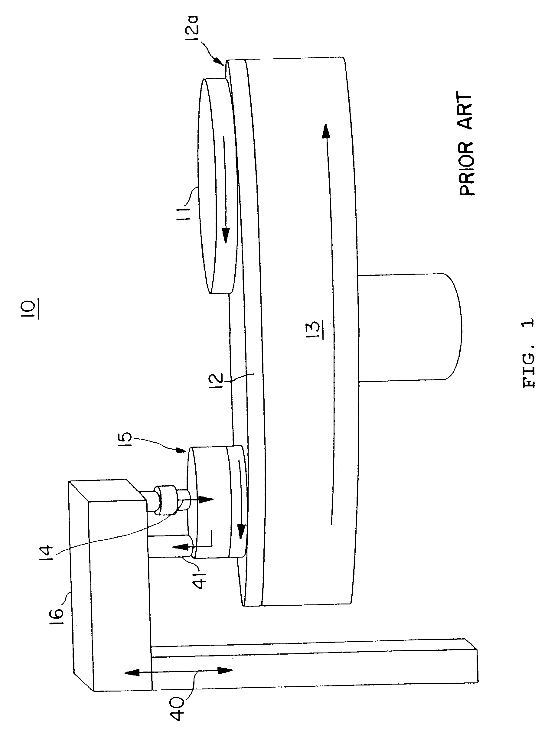
[0048]Referring to FIG. 1, a perspective view of a typical CMP system 10 is illustrated generally comprising a polishing head (not shown) that applies pressure to wafer 11 against a polishing pad 12 through a wafer carrier and support arm (not shown), and a polishing pad conditioning apparatus 15. Wafer 11 is rotated on polishing pad 12 that ...


PUM

PropertyMeasurementUnit
thicknessaaaaaaaaaa
diameteraaaaaaaaaa
pressureaaaaaaaaaa

Abstract

A method and apparatus for conditioning polishing pads that utilize an apertured conditioning disk for introducing operation-specific slurries, without the need for additional tooling, platens, and materials handling. The a method and apparatus utilize a vacuum capability to pull waste material out of the conditioning pad and through the apertured conditioning disk to evacuate the apparatus through an outlet port, the apparatus may also include self-contained flushing means and a piezo-electric device for vibrating the pad conditioning apparatus.

Description

BACKGROUND OF THE INVENTION[0001]1. Field of the Invention[0002]The present invention relates generally to the fields of semiconductor fabrication, microelectromechanical systems (MEMS) fabrication, and precision polishing; and specifically to a method for the removal of waste products from the polishing process, and for the introduction of multiple, different slurries during Chemical Mechanical Polishing (CMP) and planarization.[0003]2. Description of Related Art with Respect to Semiconductor Fabrication[0004]An integrated circuit generally consists of a silicon wafer substrate typically produced or fabricated as a disc with a diameter of 100 to 300 millimeters and a thickness of 16 to 40 mils. Metallic, dielectric and insulator depositions forming interconnected circuits are created on a wafer by a series of processes, such as lithography, vapor deposition, and oxidation, that produce the desired electrical circuitry. An electrical insulating layer, up to one-micron in thickness, ...

Claims


Application Information

Patent Timeline
Patent Type & Authority Patents(United States)
IPC IPC(8): B24B1/00B24B19/00B24B53/00B24B53/007B24B53/013B24B53/02B24B57/00H01L21/306
CPCB24B53/00B24B53/013B24B53/02B24B57/00B24B53/017H01L21/30625H01L21/304
Inventor BENNER, STEPHEN J.
Owner TBW IND INC
Why Eureka
Try Eureka