Optimized channel controller for NMR apparatus

a channel controller and nmr technology, applied in the field of magnetic resonance apparatus, can solve the problems of straining both memory capacity and transfer rate, presenting a ponderous procedure with considerable complication in the software, and reducing the bulk transfer rate burden, so as to reduce the burden of bulk transfer rate and facilitate the operation

Inactive Publication Date: 2006-05-30
AGILENT TECH INC
View PDF9 Cites 9 Cited by
  • Summary
  • Abstract
  • Description
  • Claims
  • Application Information

AI Technical Summary

Benefits of technology

[0018]The controller of the present invention narrows the above described gap in implementing two major strategies. First, the controller architecture retains elements of the state in latched registers that retain their content until rewritten to different content. This reduces the bulk transfer rate burden when the form of the state sequence is reduced to specification of the changes in the contemporaneous state over the preceding state. Second, concurrently with transactions updating other latched registers defining the state description, a computational layer of the controller executes common mathematical operations, specialized for the corresponding fields of the status bits in parallel. These computations are implemented with application specific integrated circuits, executing in parallel within a clock cycle, thereby introducing no rate limiting step(s). Further, this strategy eliminates the need for extensive data packing. As a result, the aforesaid gap is either eliminated, or reduced for manageability through high speed FIFO buffering of modest proportion.

Problems solved by technology

This presented a ponderous procedure with considerable complication in the software.
Consequently, the rate at which the state of the system may be altered is distinctly limited because multiple parameter changes require a corresponding multiple device select instructions.
The computational load and the data management burden each lead to extreme situations which strain both memory capacity and transfer rate as applied to prior art systems.
The practical limit for the apparatus is not the limit of what might be achieved, but rather the requirements of the instrumental function.
The sequential states of the NMR apparatus must be created (computed or derived from memory) and revised (scaling, phase cycling, vector rotation, etc) and these creation and revision operations are instrumentally and / or computationally intensive with resulting limits on the rate of physical state evolution controlling the apparatus.
This rate disparity or gap is accommodated by very large buffers (which also present limitations for such use).
In the limit of a large gap between a sustained state evolution rate and the control processor transfer rate, extremely massive buffering becomes economically impractical to narrow that gap.
It should be recognized that in addition to the recognizable computational burden there is a time consuming formatting task necessary to reduce computed parameters to elements of a state descriptor.

Method used


Image

  • Optimized channel controller for NMR apparatus
  • Optimized channel controller for NMR apparatus
  • Optimized channel controller for NMR apparatus

Examples


Embodiment Construction

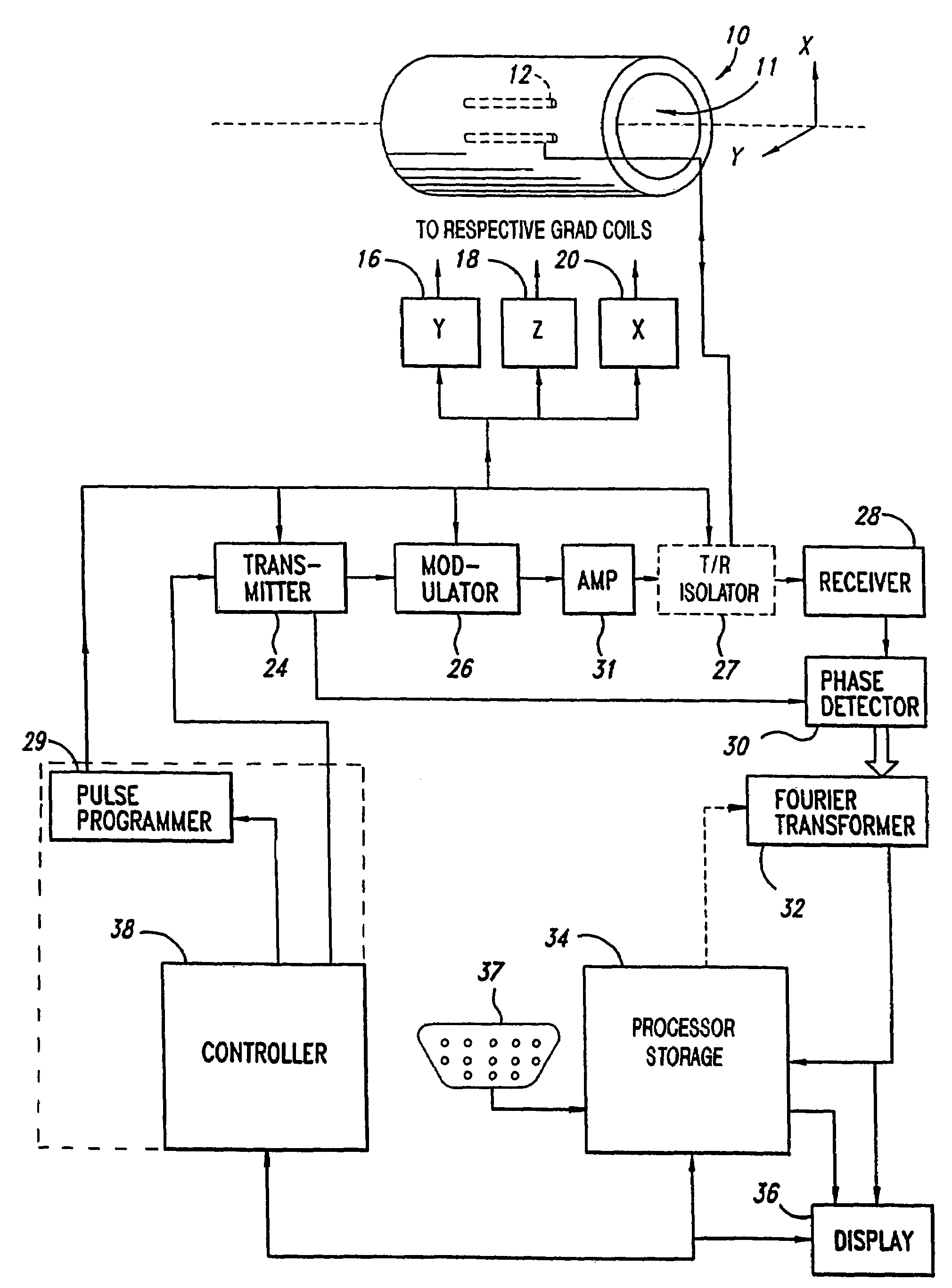
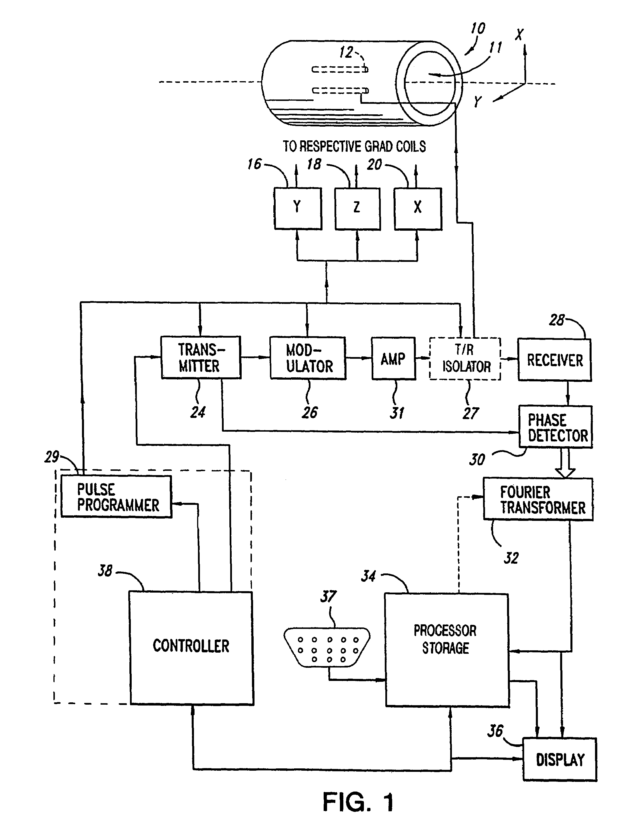
[0028]The representative physical context of the invention is an NMR apparatus that includes a number of devices to be controlled in synchrony. An idealized illustration is shown in FIG. 1. A magnet 10 having bore 11 provides a main magnetic field along the axis of the bore. In order to control the magnetic field with precision in time and direction for selected measurements requiring magnetic field gradients, there are provided magnetic field gradient coils (not shown). These are driven by gradient power supplies 16, 18 and 20, respectively. Additionally, other shimming coils (not shown) and power supplies (not shown) may be required for compensating residual undesired spatial inhomogeneity in the basic magnetic field. An object for analysis (hereafter “sample”) is placed within the magnetic field in bore 11 and the sample is subject to irradiation by RF power, such that the RF magnetic field is aligned in a desired orthogonal relationship with the magnetic field in the interior of...


PUM


Abstract

A controller for apparatus assuming a sequence of precisely synchronized states in accordance with a lengthy event stream is realized in an architecture comprising a register layer comprising a plurality of latched registers for receiving event descriptors and parameters from a bus and a computational / logical layer for operations on / among certain of said parameters for presentation to external operational devices. An RF controller controlling frequency, pulse width, amplitude with precise timing for magnetic resonance applications is one example and a magnetic gradient controller controlling vector magnitude and orientation is another.

Description

FIELD OF THE INVENTION[0001]The invention is principally in the field of magnetic resonance apparatus and relates particularly to efficient control of time sensitive functions of such apparatus.BACKGROUND OF THE INVENTION[0002]Many instrument applications require the creation and maintenance of a precisely timed event stream. Frequency agile radar, arbitrary radio frequency (RF) generation, pulsed magnetic field sources, time domain instrumentation such as NMR spectrometers, MRI imagers and the like, are a few examples. Such apparatus may be described in an instantaneous sense as existing in a well define “state”. The state in turn, is described by the quantitative condition of each of the independent variables of the apparatus. By way of a simple example, an RF synthesizer operating to produce a desired waveform from N frequency components may specify the frequency component(s), with corresponding values of amplitude, phase, state duration and perhaps a waveform repetition rate for...

Claims


Application Information

Patent Timeline
Patent Type & Authority Patents(United States)
IPC IPC(8): G01V3/00G01R33/36G01R33/54
CPCG01R33/54G01R33/3607G01R33/543
Inventor HORNUNG, PHILLIP A.
Owner AGILENT TECH INC
Why Eureka
Try Eureka