Magnetic disk storage system

a magnetic disk and storage system technology, applied in the direction of recording information storage, instruments, magnetic disks, etc., can solve the problems of insufficient electromotive force of the spindle motor, head colliding with the disk surface, and insufficient traction driver activation, so as to avoid the increase of circuit scale

Inactive Publication Date: 2006-05-30
RENESAS TECH CORP +1
View PDF6 Cites 28 Cited by
  • Summary
  • Abstract
  • Description
  • Claims
  • Application Information

AI Technical Summary

Benefits of technology

[0007]While a great increase in capacity with high densification has recently been put forward in the magnetic disk storage system, the surface of the magnetic disk is finished to a state of having a very little roughness like a mirror surface with the high densification. Since it becomes necessary to accurately control a head position with the high densification, an attempt has been made to reduce a gap between the magnetic head and the magnetic disk and improve an S / N ratio of a read / write signal. A mechanism called a vacuum slider in which the gap becomes small as the number of rotations of the disk increases, is being put to use to reduce the gap between the magnetic head and the magnetic disk.
[0011]Another object of the present invention is to provide a control technology of a voice coil motor, which is capable of moving a magnetic head to a standby position safely even if a power supply is shut off when the rotation of a spindle motor is slow, in a magnetic disk storage system.
[0012]A further object of the present invention is to provide a control technology of a voice coil motor, which is capable of moving a magnetic head to a standby position in safety even when a power supply is shut off during loading of the magnetic head, in a magnetic disk storage system wherein the loading of the magnetic head is performed in a state in which the number of rotations is reduced lower than at a normal operation.
[0013]A still further object of the present invention is to provide a control technology of a voice coil motor, which is capable of safely performing loading and unloading of a magnetic head in a magnetic disk storage system capable of high-density recording using a vacuum slider.
[0016]There is provided a magnetic disk storage system comprising a first motor like a spindle motor which rotates a magnetic disk, a first motor drive circuit which rotatably drives the first motor, a magnetic head which effects read of information on a storage track on the magnetic disk rotated by the first motor, a second motor like a voice coil motor which moves the magnetic head over the magnetic disk, a second motor drive circuit which rotatably drives the second motor, and a drive control circuit which controls currents caused to flow through coils of the first and second motors by the first motor drive circuit and the second motor drive circuit, wherein, upon loading the magnetic head from a standby position to the surface of the magnetic disk, a rotational speed of the first motor is made slower than a rotational speed at a normal operation. Thus, it is possible to avoid that the head is brought into contact with the disk surface upon loading of the magnetic head.
[0017]Preferably, the drive control circuit causes the first motor drive circuit to perform a stepup converter operation upon power shutoff to thereby generate a voltage higher than each of back electromotive voltages of the first motor, and moves the magnetic head to a predetermined standby position by the high voltage. Thus, even if power shut-off occurs during the loading of the magnetic head, the magnetic head can be retracted safely. Since the first motor drive circuit is caused to perform the stepup converter operation to thereby generate the voltage higher than the back electromotive voltage, the voltage necessary for a retract operation of the head can be obtained without providing a special stepup converter, and hence an increase in circuit scale can be avoided. Further, the control and drive device dedicated for head retraction also become unnecessary.

Problems solved by technology

Therefore, the retract driver cannot be sufficiently activated in the case of a small-sized motor in which the back electromotive force of a spindle motor is small, and when the rotation of the spindle motor is slow.
There is a possibility that when such a vacuum slider is used, the head will collide with the disk surface when the rotational speed is fast upon moving the head from the standby position to the surface of the magnetic disk.
Since, however, the power failure abruptly occurs, it might be produced during loading.
Therefore, when the power failure occurs during loading under the system for making slow the rotational speed of the disk upon loading the magnetic head, the back electromotive force of the spindle motor is not so sufficient that it becomes difficult to move the magnetic head to the standby position in safety.
The power failure might occur when the head is being moved to the outside of the disk during a seek operation.
Also the power failure might occur when the head is being moved to the inside of the disk.
Therefore, there is a need to carry out complex and high-accuracy control.
However, it became evident that a problem arose in that since the conventional retract operation made use of the voltage obtained by simply rectifying the back electromotive voltage of the spindle motor, the resultant voltage was low and only simple control of such an extent that the driver of the voice coil motor was driven to retract the head, could be performed.

Method used


Image

  • Magnetic disk storage system
  • Magnetic disk storage system
  • Magnetic disk storage system

Examples


Embodiment Construction

[0027]Preferred embodiments of the present invention will hereinafter be described with reference to the accompanying drawings.

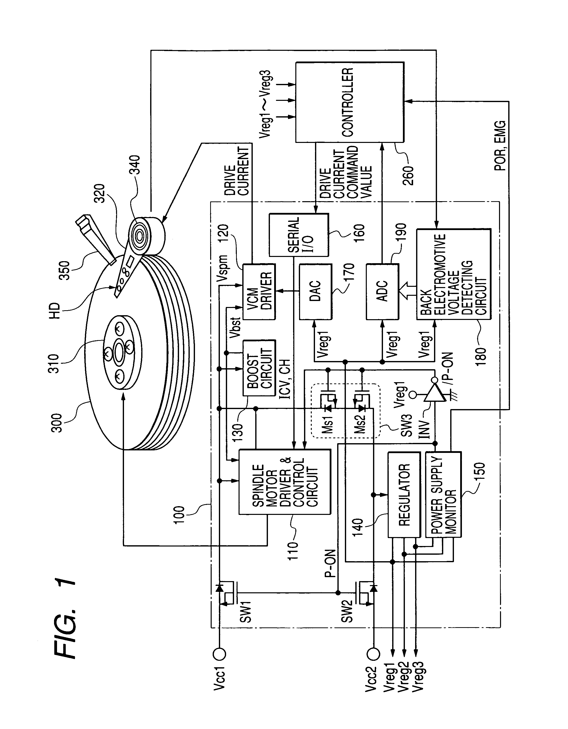
[0028]FIG. 1 shows a schematic configuration of a motor control system employed in a magnetic disk storage system to which the present invention is applied.

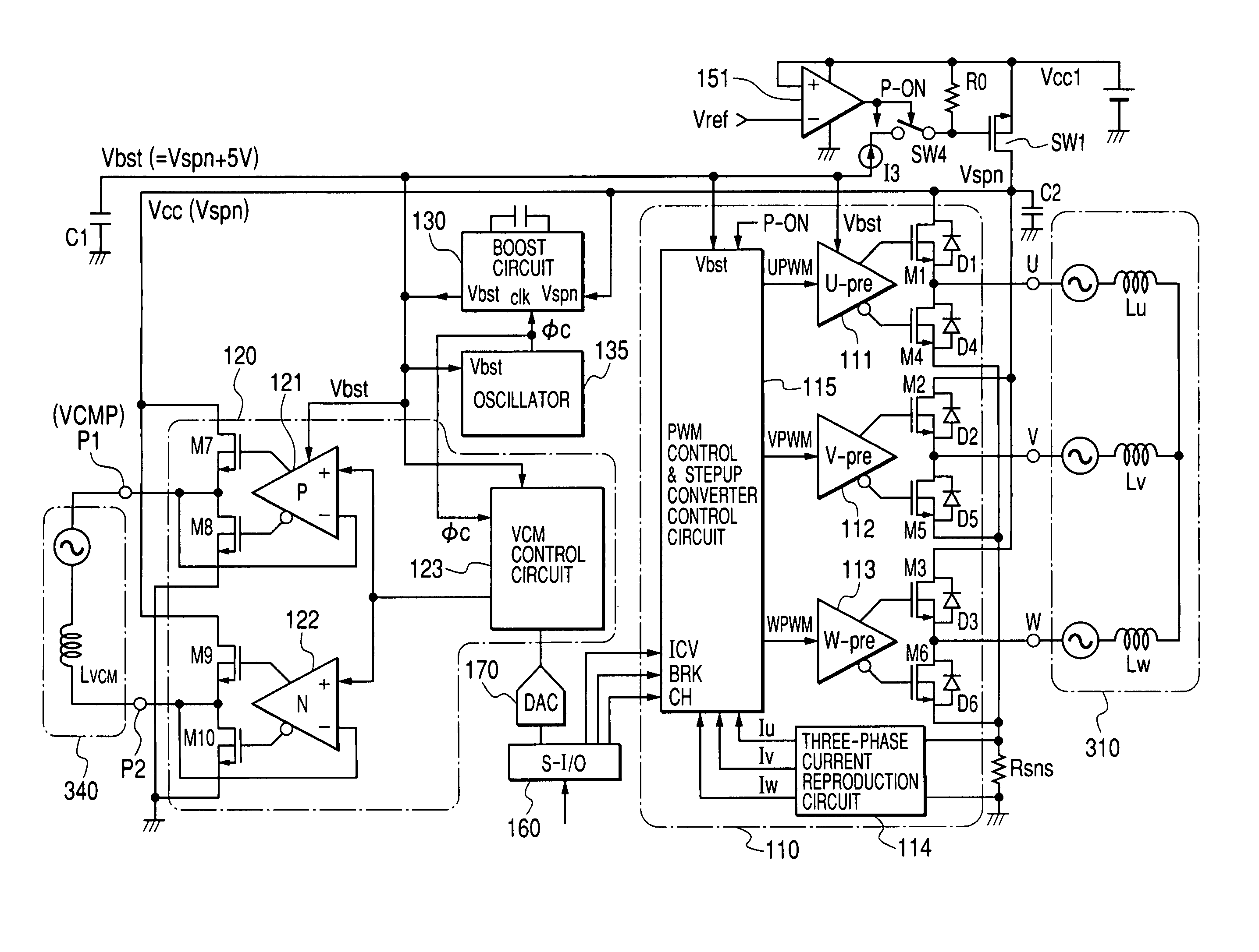
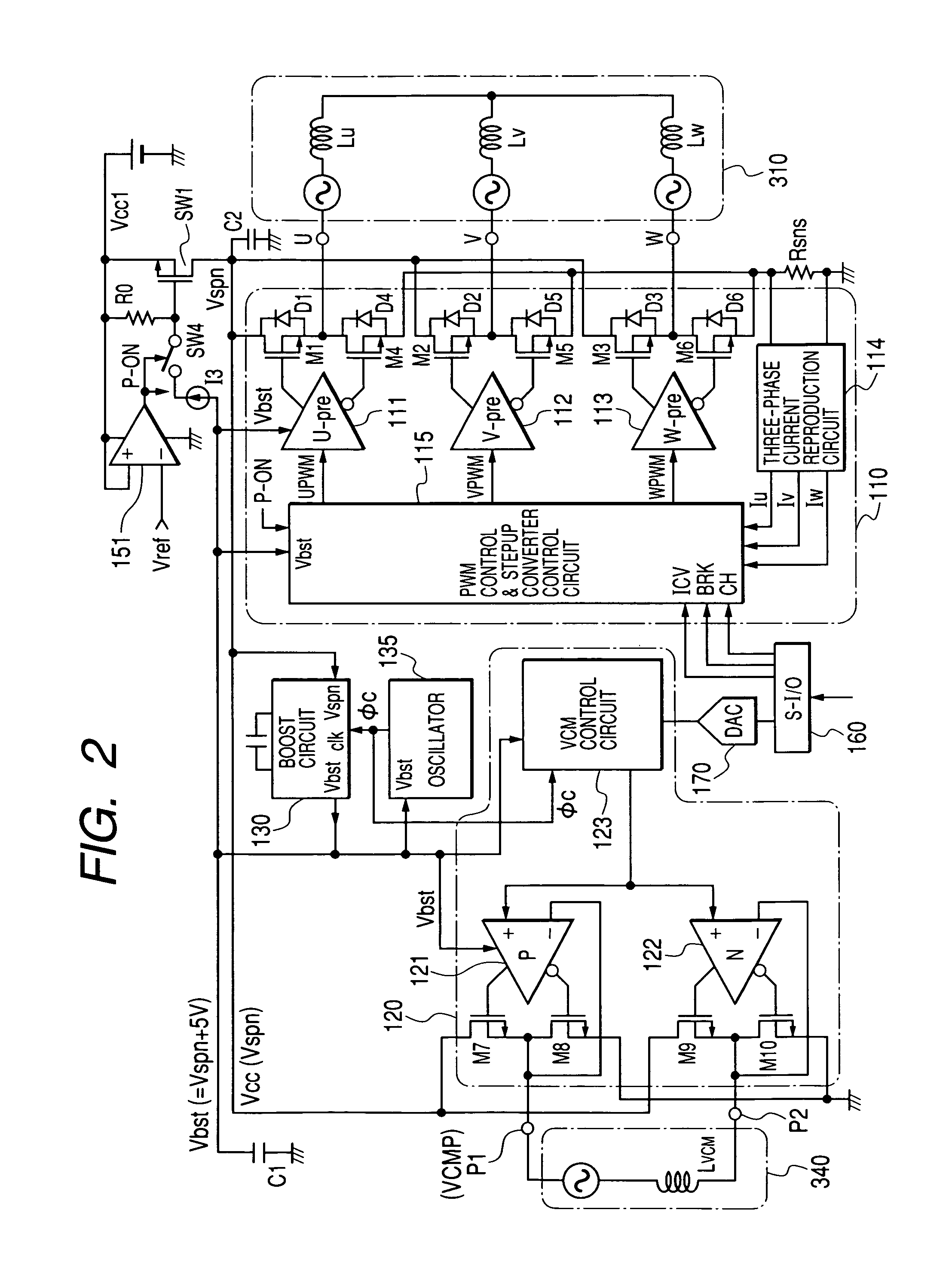
[0029]As shown in FIG. 1, the magnetic disk storage system according to the present embodiment includes a magnetic disk 300, a spindle motor 310 which rotatably drives the magnetic disk 300 at high speed, an arm 320 having, at its leading end, a magnetic head HD which effects read / write of information on a storage track on the magnetic disk 300, a voice coil motor 340 which moves the magnetic head HD over the magnetic disk 300 via the arm, a motor drive control circuit 100 brought into semiconductor integrated circuit form, which drives and controls the voice coil motor 340, a controller 260 which controls the operation of the whole magnetic disk storage system and outputs a current command value for the ...


PUM

PropertyMeasurementUnit
rotational speedaaaaaaaaaa
voltageaaaaaaaaaa
currentaaaaaaaaaa

Abstract

The present invention provides a magnetic disk storage system including a spindle motor that rotates a magnetic disk, a spindle motor drive circuit that rotatably drives the spindle motor, a magnetic head that performs reading of information on the magnetic disk, a voice coil motor that moves the magnetic head, and a voice coil motor drive circuit that drives the voice coil motor. When the magnetic head is loaded from a standby position to the surface of the magnetic disk, the rotational speed of the spindle motor is made slower than a rotational speed at a normal operation. Upon power-off, the spindle motor drive circuit is caused to carry out a stepup converter operation to thereby generate a voltage higher than a back electromotive voltage, and causes a control circuit and a drive circuit to operate by the high voltage to thereby enable speed control at the movement of the magnetic head to a predetermined standby position.

Description

BACKGROUND OF THE INVENTION[0001]The present invention relates to a control technology of a magnetic disk storage system, and a technology effective when applied to motor control at the time of shut-off of a power supply like the time of the occurrence of power failure, e.g., a technology effective for use in retraction control of a magnetic head by a voice coil motor for moving the magnetic head that effects read / write of information on a storage track on a magnetic disk in a hard disk drive.[0002]A magnetic disk storage system includes a voice coil motor for moving (seek-operating) a magnetic head that effects read / write of information on a storage track on a magnetic disk, in a radial direction along the surface of the magnetic disk in addition to a spindle motor for rotatably driving the magnetic disk. In a hard disk drive, the magnetic head is configured so as to glide on the surface of the disk with wind pressure developed with the rotation of the disk. Thus, there is a possib...

Claims


Application Information

Patent Timeline
Patent Type & Authority Patents(United States)
IPC IPC(8): G11B15/46G11B21/12G11B5/54G11B5/55G11B19/22G11B21/02
CPCG11B5/54G11B21/02G11B5/5526
Inventor KOKAMI, YASUHIKO
Owner RENESAS TECH CORP
Why Eureka
Try Eureka