Shaft sealing apparatus

a shaft sealing and shaft technology, applied in lighting and heating apparatus, charge manipulation, furniture, etc., can solve the problems of increasing the size of conventional shaft sealing apparatus, so as to achieve excellent characteristic

Inactive Publication Date: 2006-06-06
TEIJIN SEIKI CO LTD
View PDF31 Cites 24 Cited by
  • Summary
  • Abstract
  • Description
  • Claims
  • Application Information

AI Technical Summary

Benefits of technology

[0018]It is, therefore, an object of the present invention to provide a shaft sealing apparatus that is ...

Problems solved by technology

The conventional shaft sealing apparatus thus constructed, however, encounters such a problem that the conventional shaft sealing apparatus is complicated in construction and thus increased in size, resulting from the fact that the conventional shaft sealing apparatus is required to comprise a number of magnetic fluid seals axially disposed in series between the driving shaft and the shaft housing.
The conventional shaft sealing apparatus described in the above encounters another problem that the conventional shaft sealing apparatus is difficult to assemble, resulting from the fact that the conventional shaft sealing apparatus is complicated in construction and thus large in size.
The conventional shaft sealing apparatus described in the above encounters further problem that the driving shaft cannot be axially movably supported by the shaft housing, resulting from the fact that the magnetic fluid seals intervene between the driving shaft and the shaft housing.
The conventional shaft sealing ...

Method used


Image

  • Shaft sealing apparatus
  • Shaft sealing apparatus
  • Shaft sealing apparatus

Examples


first embodiment

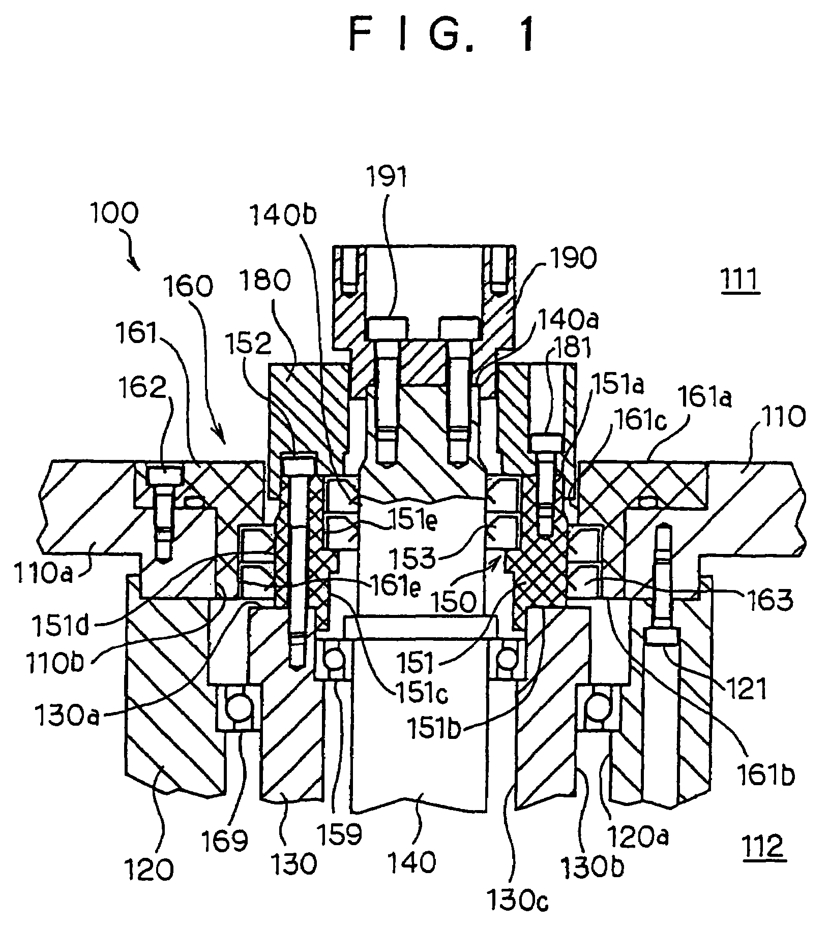
[0052]In the shaft sealing apparatus according to the present invention, the outer cylindrical surface 140b of the center shaft 140 is smaller in surface roughness Ra defined in Japanese Industrial Standard (JIS) B 0601 than 0.1 μm, and the outer cylindrical surface 140b of the center shaft 140 is larger in Vickers hardness Hv defined in JIS Z 2244 than 650.

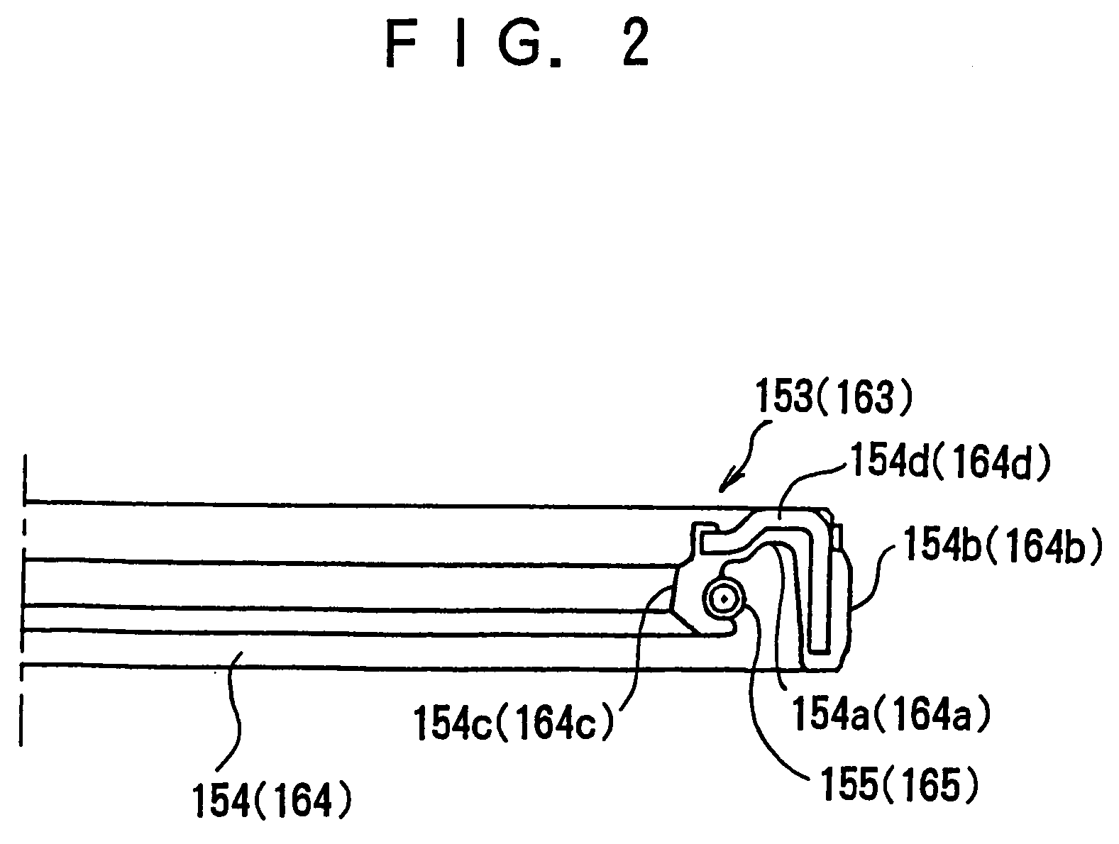
[0053]The sealing lip 154c of the annular resilient member 154 may be held in contact with the outer cylindrical surface 140b of the center shaft 140 with a vacuum grease constituted by a lubricant containing fluorine. The first sealing unit 150 may include a plurality of sealing rings 153 each having a sealing lip 154c coated with the vacuum grease. The first sealing unit 150 may also include a plurality of sealing rings 153 each having a sealing lip 154c to have the sealing lips 154c collectively form an annular groove filled with the vacuum grease. The first sealing unit 150 may also include a plurality of sealing rings 153 ea...

second embodiment

[0081]The second embodiment directed to a driving shaft received in the shaft housing 120 is shown in FIG. 6.

[0082]In FIG. 6, the shaft sealing apparatus 200 comprises a driving shaft 240 in the form of a cylindrical shape and received in the shaft housing 120, not shown, to be movably supported by the shaft housing 120. The driving shaft 240 is held in coaxial alignment with the shaft housing 120 and rotatable around its own axis with respect to the shaft housing 120. The driving shaft 240 has a first axial end 240a extending in the vacuum chamber 111 of the vacuum casing 110, a second axial end, not shown, extending in the atmosphere 112, and an outer cylindrical surface 240b smaller in diameter than the inner cylindrical surface 120a of the shaft housing 120.

[0083]The shaft sealing apparatus 200 further comprises a sealing unit 260 received in the opening 110b of the vacuum casing 110 and fixedly supported by the base portion 110a of the vacuum casing 110. The sealing unit 260 in...

third embodiment

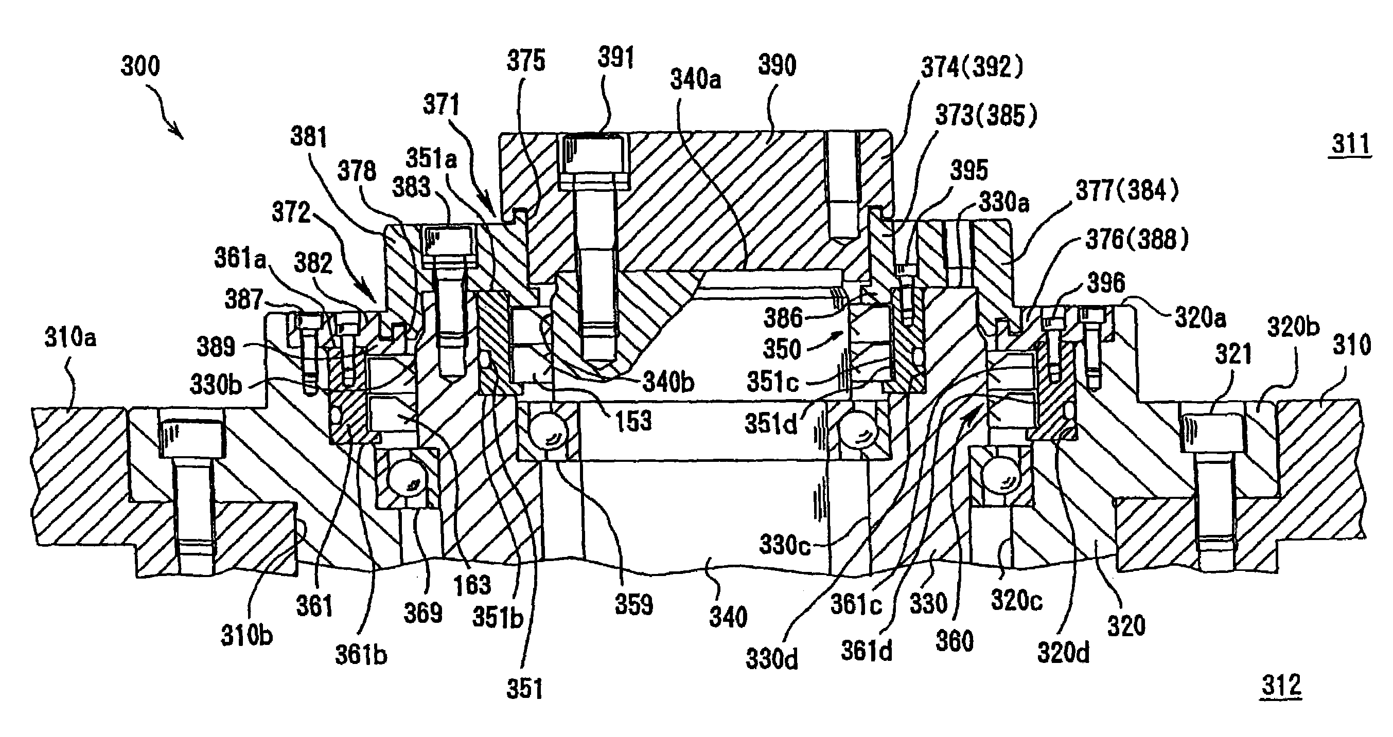
[0104]In the shaft sealing apparatus according to the present invention, the outer cylindrical surface 340b of the center shaft 340 is smaller in surface roughness Ra than 0.1 μm and larger in Vickers hardness Hv than 650.

[0105]The sealing lip 154c of the annular resilient member 154 may be held in contact with the outer cylindrical surface 340b of the center shaft 340 with a vacuum grease constituted by a lubricant containing fluorine. The first sealing unit 350 may include a plurality of sealing rings 153 each having a sealing lip 154c coated with the vacuum grease. The first sealing unit 350 may also include a plurality of sealing rings 153 each having a sealing lip 154c to have the sealing lips 154c collectively form an annular groove filled with the vacuum grease. The first sealing unit 350 may also include a plurality of sealing rings 153 each having a sealing lip 154c and a subsidiary sealing lip held in contact with the outer cylindrical surface 340b of the center shaft 340 ...


PUM


Abstract

Herein disclosed is a shaft sealing apparatus which comprises a vacuum casing formed with a vacuum chamber, a driving shaft having an outer cylindrical surface and movably extending in the vacuum chamber of the vacuum casing, and a sealing ring in the form of an annular ring shape and including a sealing lip held in contact with the outer cylindrical surface of the driving shaft, an annular spring member operative to impart a force to the sealing lip to ensure that the sealing lip is held in tight contact with the outer cylindrical surface of the driving shaft, and a peripheral portion radially outwardly extending from the sealing lip, in which the outer cylindrical surface of the driving shaft is smaller in surface roughness Ra than 0.1 (μm).

Description

[0001]This application is a divisional of application Ser. No. 09 / 981,807, filed Oct. 19, 2001, the disclosure of which is incorporated herein by reference.BACKGROUND OF THE INVENTION[0002]1. Field of the Invention[0003]The present invention relates to a shaft sealing apparatus, and more particularly to a shaft sealing apparatus for sealing the gaps between a driving shaft and other parts around the driving shaft to have the driving shaft movably extending in a vacuum chamber and operatively connected with a handling mechanism disposed in the vacuum chamber.[0004]2. Description of the Related Art[0005]Up until now, there have been proposed a wide variety of conventional shaft sealing apparatuses each designed to seal the gaps between a driving shaft and other parts around the driving shaft to have the driving shaft movably extending in a vacuum chamber and operatively connected with a handling mechanism disposed in the vacuum chamber.[0006]The conventional shaft sealing apparatuses ...

Claims


Application Information

Patent Timeline
IPC IPC(8): F16J15/32B25J19/00B01J3/00B01J3/02B01J3/03B65G49/07F16C33/72F16J15/00F16J15/3212F16J15/3236H01L21/677
CPCF16J15/006F16J15/3212F16J15/3232F16J15/324F16J15/54F16J15/3236Y10S277/913H01L21/68792F16J15/00
Inventor WATANABE, TETSUYAMORI, HIROKIOKUNO, CHOHEI
Owner TEIJIN SEIKI CO LTD
Why Eureka
Try Eureka