Covered endoprosthesis and delivery system

a technology of endoprosthesis and delivery system, which is applied in the field of endoprosthesis, can solve the problems of increasing the fluid pressure in the portal vascular circulation, increasing the risk of recurrence, and requiring a long time to cure, and achieving the effect of recurrence, reducing the risk of recurrence, and reducing the effect of recurren

Inactive Publication Date: 2006-06-06
WL GORE & ASSOC INC
View PDF28 Cites 69 Cited by
  • Summary
  • Abstract
  • Description
  • Claims
  • Application Information

AI Technical Summary

Benefits of technology

[0006]Unfortunately, for many patients conventional TIPS procedures may provide fairly short-lived improvements. Stenosis or occlusion may occur in up to half of all patients within 6 months following TIPS creation. Blockage of the shunt normally occurs due to pseudointimal formation or intimal hyperplastic response.

Problems solved by technology

It is known that diseased or damaged liver tissue may increase the resistance to hepatic perfusion resulting in excessive and often dangerous fluid pressure increases in the portal vascular circulation.
Unfortunately, for many patients conventional TIPS procedures may provide fairly short-lived improvements.
Nishimine et al. also reported that the two-step deployment of their stent-grafts (that is, deploying a graft with anchoring stents first and then separately deploying WALLSTENT stents within the graft as a second procedure) was “cumbersome and technically challenging.” Nevertheless, as the authors explained, this two-part procedure was necessary in order to allow placement of the stent and graft combination through a small 10-French (F) (3.3 mm) sheath.
However, a number of problems are presented to someone attempting to provide an improved TIPS stent-graft.
First, as Nishimine et al. reported, small profile delivery of a stent-graft device is difficult to accomplish in a single step.
While Nishimine et al. achieved delivery of a stent and graft through a 10-F sheath, this was accomplished through a cumbersome and challenging two-step procedure in which the separate devices were combined in-situ.
Premature device occlusion or shunt malfunction may be caused by a variety of conditions, including: failing to maintain proper flow into and out of the shunt device; failing to position the device to completely cover the intrahepatic tract between the portal and hepatic veins; or extending the device too far in the portal circulation or inferior vena cava.
Maintaining bile-exclusion while also seeking to use very thin graft materials in order to achieve small device delivery profiles presents a critical design challenge.
Fourth, the stent-graft also needs to have sufficient structural strength to resist distortion during use.
Thus, the choice of cover material, as well as its method of attachment to the underlying stent, present design challenges.

Method used


Image

  • Covered endoprosthesis and delivery system
  • Covered endoprosthesis and delivery system
  • Covered endoprosthesis and delivery system

Examples


example 1

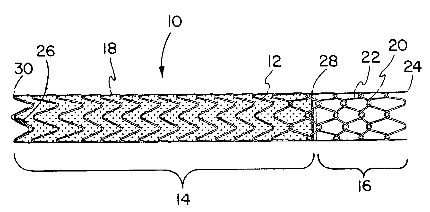
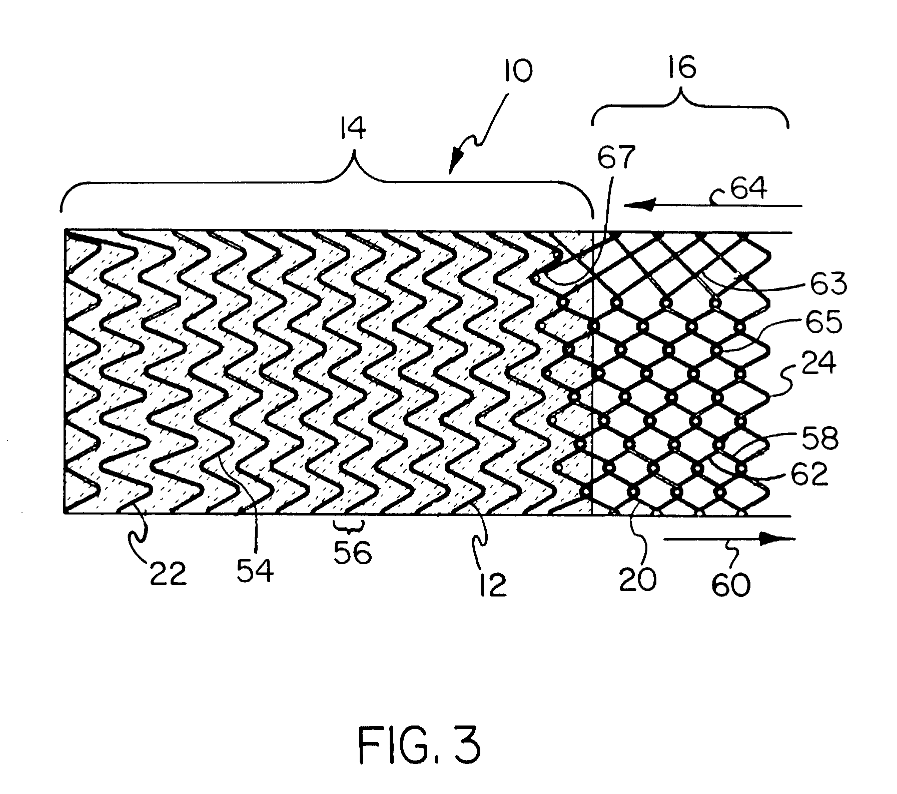
[0116]A pin jig is manufactured by turning 304 stainless steel rod stock to an 8 mm diameter. Holes are then drilled in the mandrel (#67 bit) to create the pattern to wind the stent depicted in FIG. 3, with 5 forward facing apices (10 holes) per revolution. Beyond each end of the hole pattern on the mandrel, holes are drilled and tapped to fit 10–32 screws. 1 / 32 inch (0.79 mm) diameter×4 mm length steel pins are then place into these holes, such that 2 mm of the pins are imbedded in the mandrel.

[0117]Nitinol wire of a 0.010″ (0.25 mm) nominal diameter (acquired from Nitinol Devices and Components, Fremont, Calif.) is then wound by hand around this pin jig in the pattern shown in FIG. 3 and the ends of the wire affixed in a tight configuration to the mandrel by 10–32 screws. The wire and the mandrel is then set in a convection oven set a 450° C. for 15 minutes, followed by a rapid quench in ambient temperature water. After the mandrel is allowed to cool, the wire stent is removed fro...

example 2

[0146]A device similar to the one in described in Example 1 is made, however, the inner diameter is 10 mm, the stent pattern has 6 apices per revolution, the wire diameter is 0.011 inches (0.28 mm), and the tapered die has 6 nylon lines (spacing=60°). Testing is perform as described above, with the following results:

[0147]

10 mm DeviceKink Diameter20 mmRadial StiffnessCovered section-0.173 kg / mmdiameterUncovered section-0.258 kg / mmdiameterPermeability143 sec per 100 cc air per 1 cm2materialProfile3.6 mmBent FibrilsAverage ratio V / H = 0.176Internal Corrugation99% of original

example 3

[0148]A device similar to the one in Example 1 is made; however, the inner diameter is 12 mm, the stent pattern has 6 apices per revolution, the wire diameter is 0.010 inches (0.25 mm), and the tapered die has 6 nylon lines (spacing=60°). Testing is performed as described above, with the following results:

[0149]

12 mm DeviceKink Diameter24 mmRadial StiffnessCovered section-0.103 kg / mmdiameterUncovered section-0.157 kg / mmdiameterPermeability111 sec per 100 cc air per 1 cm2materialProfile3.6 mmBent FibrilsAverage ratio V / H = 0.234Internal Corrugation98% of original


PUM


Abstract

The present invention is an improved endovascular device particularly useful for use in transjugular intrahepatic portosystemic shunt (TIPS) procedures. The device employs a two-part stent-graft construction that provides a low permeability membrane to line the shunt and an uncovered stent portion designed to reside in the portal vein. The device provides numerous benefits over previous stents and stent-grafts used in TIPS procedures, including being more compact to deliver, being easier to accurately deploy, a controlled compacted surface with tucked apices, an improved stent winding pattern, and being more flexible in delivery and use.

Description

RELATED APPLICATIONS[0001]The present application is a continuation of application Ser. No. 09 / 489,604, filed Jan. 20, 2000 and issued as U.S. Pat. No. 6,673,102, which is a continuation-in-part of application Ser. No. 09 / 235,219, filed Jan. 22, 1999 and now abandoned.BACKGROUND OF THE INVENTION[0002]1. Field of the Invention The present invention relates to endoprostheses such as stents and stent-grafts, and particularly to endoprostheses that are suitable for use in transjugular intrahepatic portosystemic shunt (TIPS) applications.[0003]2. Description of Related Art[0004]It is known that diseased or damaged liver tissue may increase the resistance to hepatic perfusion resulting in excessive and often dangerous fluid pressure increases in the portal vascular circulation. This condition can lead to gastrointestinal variceal hemorrhage and pathological conditions such as ascites.[0005]In order to decompress the portal circulation, a transjugular intrahepatic portosystemic shunt (TIPS...

Claims


Application Information

Patent Timeline
Patent Type & Authority Patents(United States)
IPC IPC(8): A61F2/06A61F2/90
CPCA61F2/07A61F2/844A61F2/88A61F2230/0054A61F2/89A61F2/90A61F2002/075A61F2002/072
Inventor ARMSTRONG, JOSEPH R.CULLY, EDWARD H.GALLEGOS, MARGARET L.VONESH, MICHAEL J.
Owner WL GORE & ASSOC INC
Why Eureka
Try Eureka