
Water heater

a technology for water heaters and water heaters, applied in the field of water heaters, can solve the problems of frequent failure and repair, heating element corrosion of various types, and requiring costly repairs, so as to eliminate the risk of leakage and busted fittings, and eliminate the risk of heating element corrosion

Inactive Publication Date: 2006-06-06
DYMAS FUNDING COMPANY
View PDF30 Cites 60 Cited by
  • Summary
  • Abstract
  • Description
  • Claims
  • Application Information

AI Technical Summary

Benefits of technology

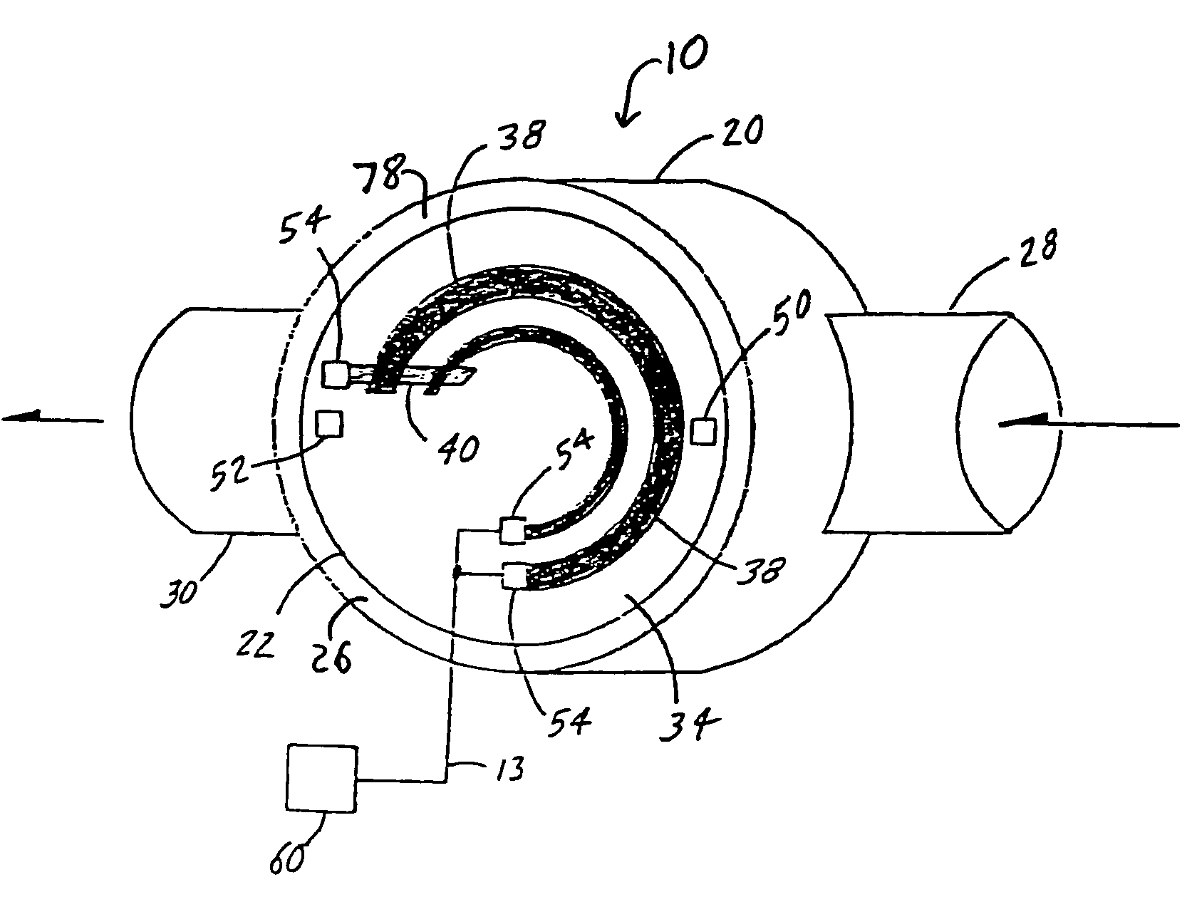
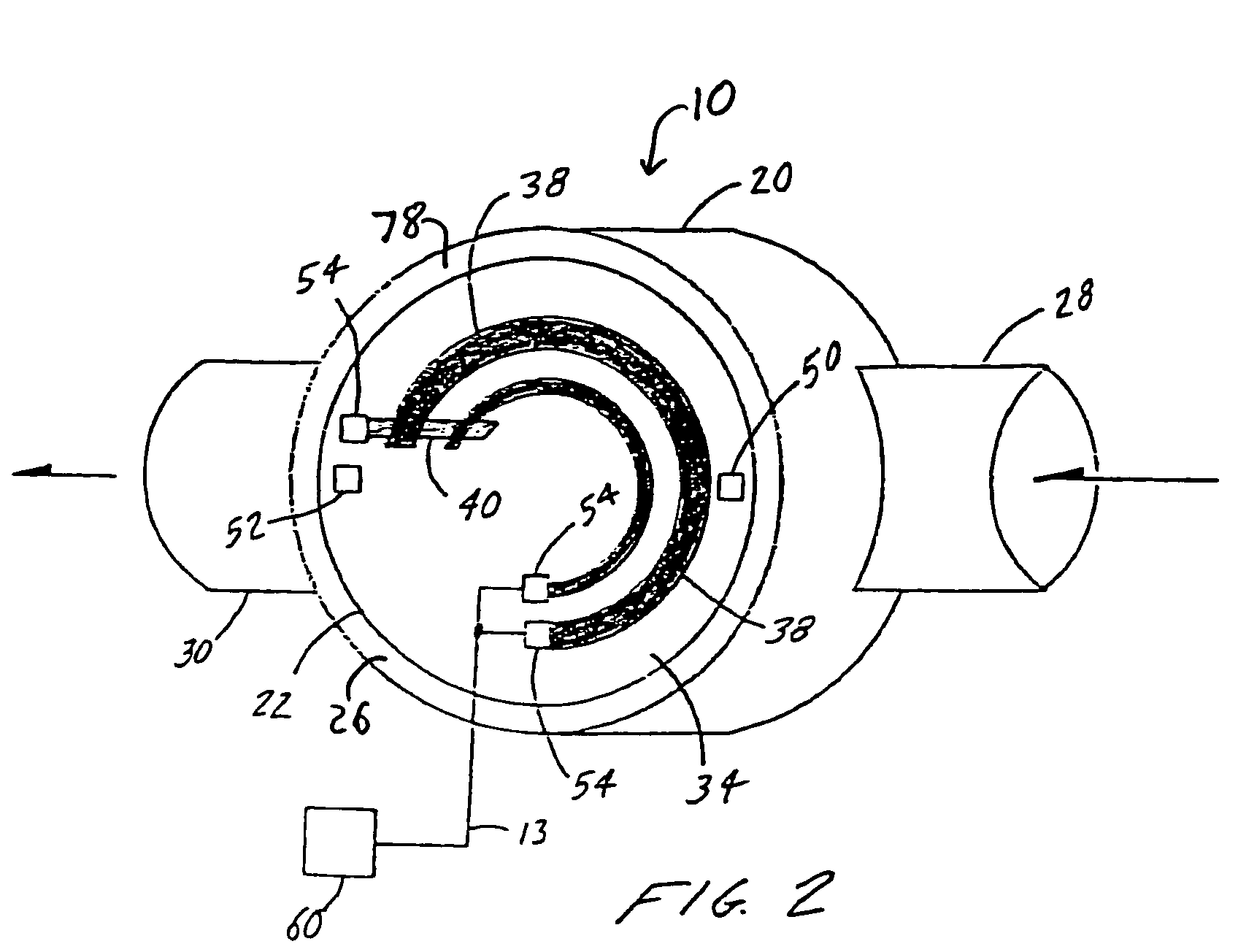
[0011]The present invention specifically addresses and alleviates the above mentioned deficiencies associated with the prior art. In this regard, the present invention comprises a new and improved use of a heating element technology known as “thick film on substrate construction,” applied to a spa heater. The thick film on substrate heating element comprises an electrical resistance layer of material affixed to a substrate, which can be a plate or pipe made of metallic material such as stainless steel. Electricity is passed to the resistive layer by an electrical lead terminal on the outside of the substrate plate or pipe, which eliminates the need for bulkhead fittings to pass electrical charge into the inner surface or wet region of the spa heater. This invention also eliminates the risk of leaks and busted fittings by providing a smooth inner heating surface with no bulkheads and no electric current passing through the wall into the wet region of the heater. By eliminating passing electricity into the wet region, the risk of corrosion of the heating element is eliminated. Temperature sensors such as thermistors are also attached directly to the substrate for monitoring the temperature and providing temperature data to a power controlling device. Other temperature sensing devices can be used instead of or in conjunction with thermistors. Alternatively, temperature sensors can be passed into the water flow path at locations near the heater to get direct water temperature readings without the need to replace the heater if a temperature sensor should fail or develop a leak. A glass or other insulating material overcoating can be applied to the top of the resistive and conductive elements to provide further insulation and protection from other environmental factors.
[0012]According to an embodiment of the invention, the thick film on substrate heating elements are in the form of plates coupled to a heating chamber with inflow and outflow pipes attached to the heating chamber to allow water to enter the heating chamber. This arrangement provides a smooth seamless inner heating surface without the need to pass electrical leads into the wet region of the heater. Such arrangement further eliminates the need for bulkhead fittings and prevents corrosion of the heating element by maintaining a physical barrier between the “dry” electrical portion of the heater and the “wet” water flow portion of the heater. An electrical line is connected to the conductive layer and resistors to energize the system and heat the substrate, which is in direct contact with the spa water to be heated. This smooth surface direct contact between the spa water to be heated and the heating element or substrate provides efficient heat transfer to the spa water due to the large surface area of interaction between the substrate and the spa water. An added benefit of not having bulkhead fittings and a heating element in the water flow path is that there is no reduction in flow rate due to obstructions within the water flow path.

Problems solved by technology

Due to extensive building safety code regulations and high initial setup costs for gas heating water for spas, the majority of spas use heaters that employ electric heat in some form or fashion.
However, the reason for this method's efficiency is also the reason for its frequent failure and need for repairs.
Because the heating element is surrounded by chemically treated water at high temperatures, the heating element is subject to various types of corrosion, including: galvanic corrosion, chemical pitting, intergranular corrosion, stress corrosion cracking, corrosion fatigue, electrochemical corrosion, and bacterial corrosion due to Ferrobacillus bacteria.
This corrosion exposure is one of the most common and most frequent causes of spa breakdown, which generally requires a costly repair due to pipes needing to be cut to expose the heating element, or replacement of the entire heater apparatus.
Furthermore, this method is prone to leaks and failures due to the need for bulkheads to allow the electric line(s) to pass from the outer-dry surface to the inner-wet surface, so the heating element can be surrounded by the water that is to be heated.
The bulkheads are another common source of failure in spa heaters, which make them susceptible to leaks and water intrusion.
Although this method eliminates the need for bulkheads and electrical lines passing through the water retaining surface, this method provides a very inefficient means of heating water due to the minimal amount of surface area contact between the heating element loops and the flow pipe, resulting in most of the heat being dissipated to the surrounding air or insulation.
This method is inefficient due to minimal contact area between the water and the heating surface.
This method of heating spa water is inefficient due to the distance between the heating element and the water passageways, and the amount of solid heat conductive material that must be heated in order for heat to radiate to the water flowing through the water passageways.
Furthermore, this method is very expensive to manufacture and requires strict dimensional and bore tolerances to maximize the surface contact area to transfer as much heat as possible from the heating element to the flow pipes.
The repair cost for this system can be quite costly as well due to the elaborate piping through a solid aluminum conductive member.

Method used


Image

  • Water heater
  • Water heater
  • Water heater

Examples


Embodiment Construction

[0027]The following detailed description and accompanying drawings are provided for purposes of illustrating and describing presently preferred embodiments of the invention and are not intended to limit the scope of the invention in any way. It will be recognized that further embodiments of the invention may be used.

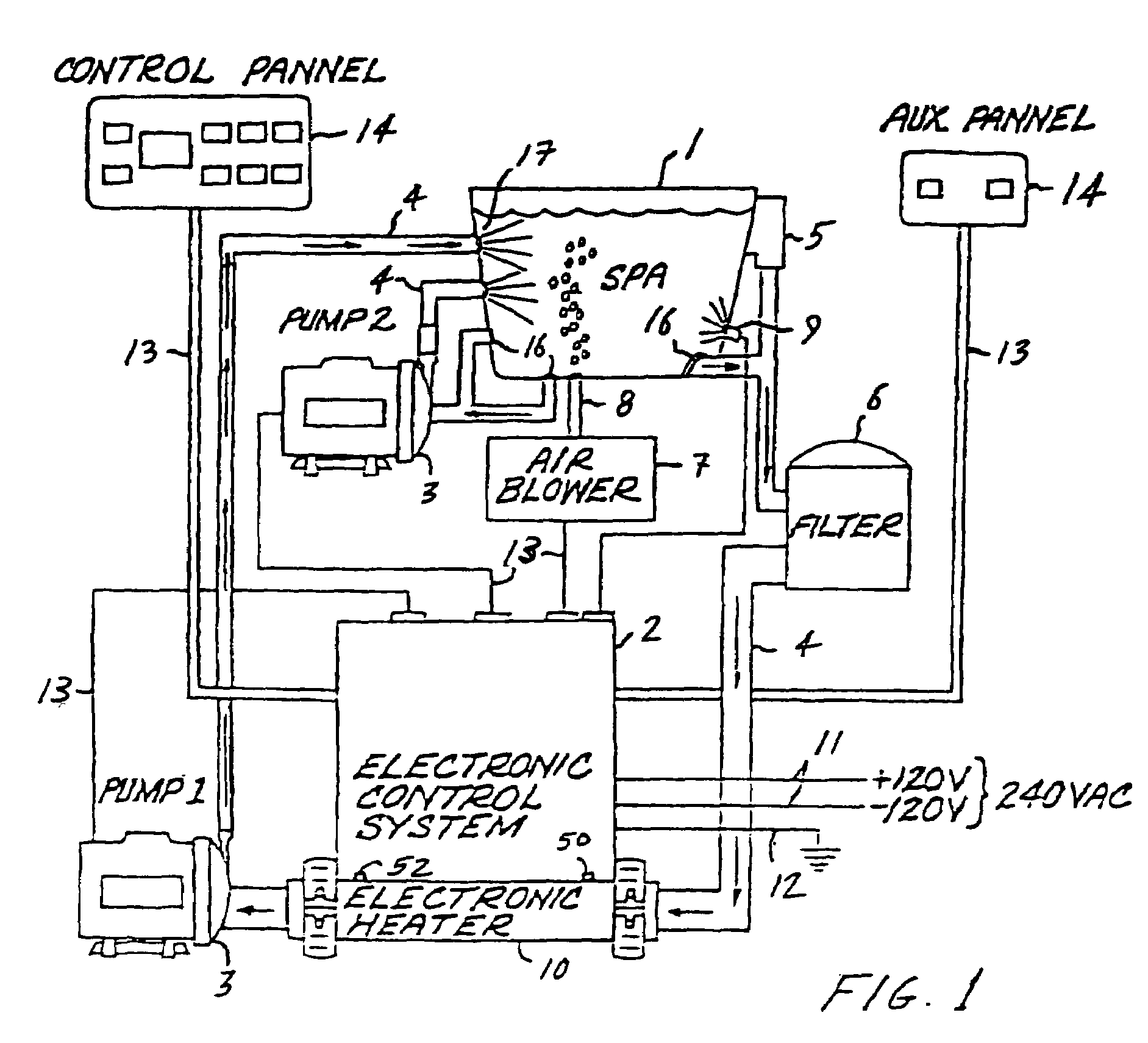
[0028]Referring now to the drawings wherein FIG. 1 is a diagram of a spa system showing the spa heater 10 with typical equipment and plumbing installed. The system includes a vessel for holding water 1 and a control system 2 with one or more microprocessors 58 to activate and manage various spa components and adjust and maintain various parameters of the spa. Connected to the vessel for holding water 1 through a series of plumbing lines 4 are one or more pumps 3 for pumping water, a skimmer 5 for cleaning the surface of the spa, a filter 6 for removing particulate impurities in the water, an air blower 7 for delivering therapeutic bubbles to the spa through one or more a...


PUM


Abstract

An improved water heater for use in spas, hot tubs, pools, hydrotherapy pools, bath tubs, and similar bodies of water used indoors, outdoors, or both indoors and outdoors are used for both therapeutic and recreational purposes. The water heater uses heating element technology know as thick film on substrate comprising resistive elements bonded to the outer dry surface of a substrate to heat the substrate which in turn heats the water flowing through the heating chamber. The heater is highly efficient due to the direct contact of the wet heating surface with the water and provides a smooth seamless inner heating surface by eliminating the need to pass electrical leads into the wet region of the heater. This virtually eliminates the risk of leaks in the water heater due to bulkhead fittings. The invention further eliminates the need for a heating element to be contained in the inner wet region of a spa heater, thereby reducing the risk of corrosion. The water heater can be used with electrical, electro-mechanical, and mechanical control systems for spas and can be retrofitted into existing spa applications.

Description

CROSS-REFERENCE TO RELATED APPLICATIONS[0001]This application claims the benefit of U.S. Provisional Patent Application No. 60 / 215,636 filed Jun. 30, 2000, the entire contents of which are incorporated herein by this reference.FIELD OF THE INVENTION[0002]The present invention relates generally to water heaters and methods of heating water in spas, hot tubs, pools, hydrotherapy pools, bath tubs, and similar bodies of water, and more particularly, to new uses of a heating element constructed of a thick film resistive layer on a substrate technology applied to water heaters.BACKGROUND OF THE INVENTION[0003]Spas, hot tubs, pools, hydrotherapy pools, bath tubs, and similar bodies of water used indoors, outdoors, or both indoors and outdoors are used for both therapeutic and recreational purposes (all forms of the aforementioned and derivatives thereof are referred to hereinafter as “spas”). When used for these purposes, the spa water is typically heated from ambient temperature to a desi...

Claims


Application Information

Patent Timeline
IPC IPC(8): H05B1/02H05B3/26H05B3/28
CPCH05B3/26H05B3/28H05B2203/021H05B2203/013H05B2203/017H05B2203/005
Inventor PITTMAN, ROBERT
Owner DYMAS FUNDING COMPANY
Learn More