Programmable/tunable active RC filter

a filter circuit and programmable/tunable technology, applied in the field of analog filter circuits, can solve the problems of reducing control efficiency, increasing the number of circuit devices, and becoming difficult to design in an integrated circuit, so as to increase the level of tuning accuracy, reduce the size of the circuit, and improve the effect of control resolution

Inactive Publication Date: 2006-06-06
IND TECH RES INST
View PDF5 Cites 19 Cited by
  • Summary
  • Abstract
  • Description
  • Claims
  • Application Information

AI Technical Summary

Benefits of technology

[0009]Another one of the purposes of the present invention is to provide a filter circuit having an utility of tuning the cut-off frequency that can narrow the tuning range of the cut-off frequency and increase the level of tuning accuracy with a constant number of control bits for achieving a higher control resolution.
[0010]Still another one of the purposes of the present invention is to provide a fine tune apparatus having a linear relation with the cut-off frequency of a filter circuit; in this regard, it can precisely tune the cut-off frequency to a desired value for compensating the parameter variations due to the manufacture process or the environments. Besides, it has a smaller circuit area under the same accuracy.

Problems solved by technology

It is therefore that, it will increase the number of devices of the circuits and reduce the control efficiency; thus, it will make it become difficult to design in an integrated circuit.
In addition, since the cut-off frequency of such kind of filters can only be tuned within a fixed range, the applications of that are limited in the kind of filters.
Therefore, it can not only increase the control efficiency and reduce the area of the circuits, but also extend the tuning range of cut-off frequency and add the applications of the circuits for the multi-function purpose.

Method used


Image

  • Programmable/tunable active RC filter
  • Programmable/tunable active RC filter
  • Programmable/tunable active RC filter

Examples


Embodiment Construction

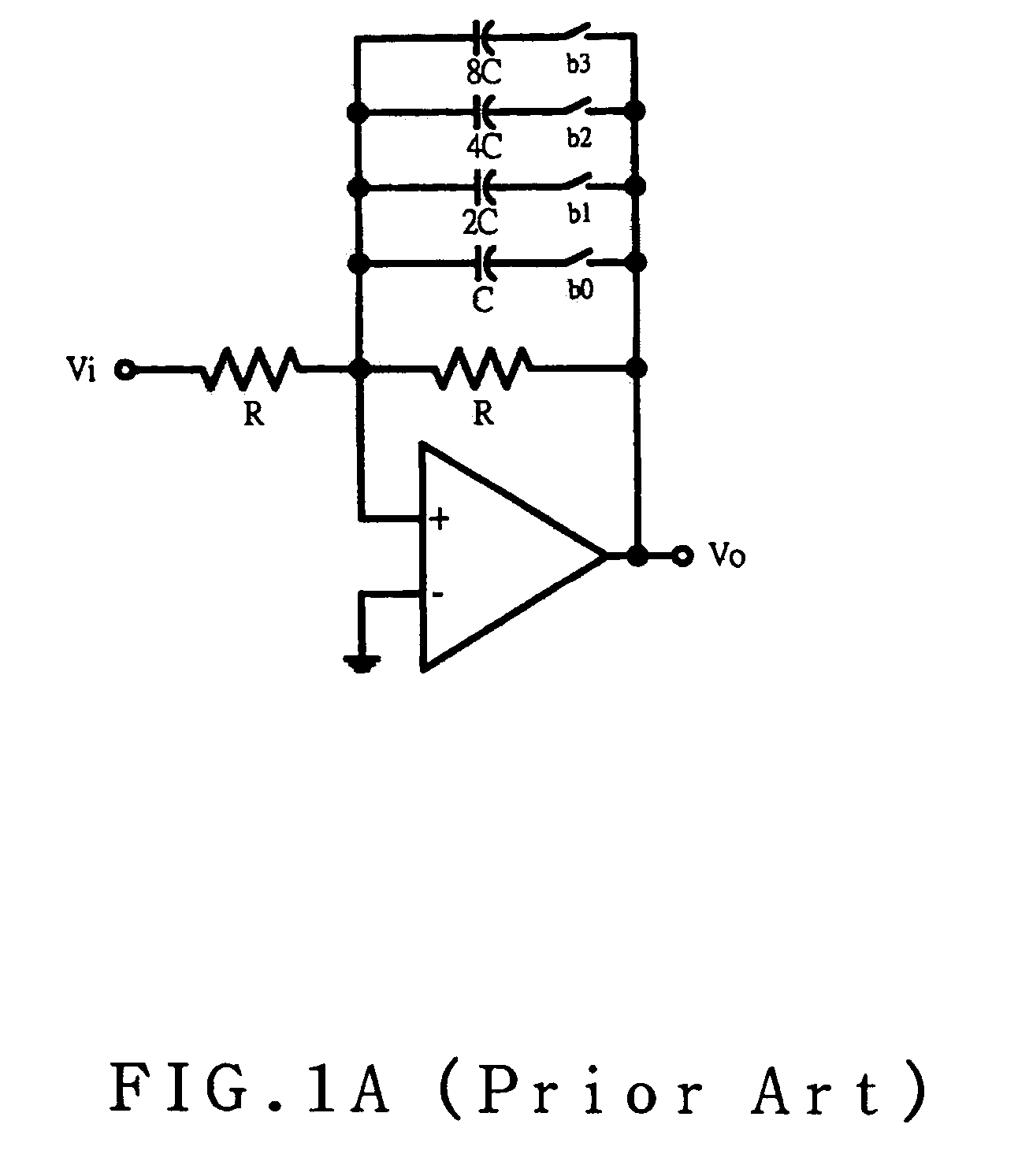
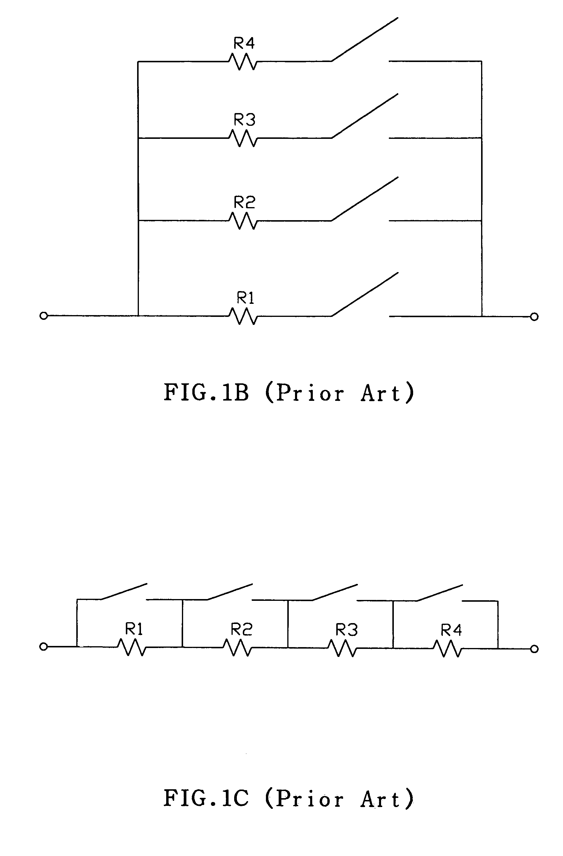
[0021]The following descriptions about the circuit of present invention not include the complete structure of the active filter. It just quotes the key points of traditional techniques for illustrates the present invention. Moreover, all of the drawings relates to the present invention don't accord the scale, they are just used to represent the characteristics of structure of present invention.

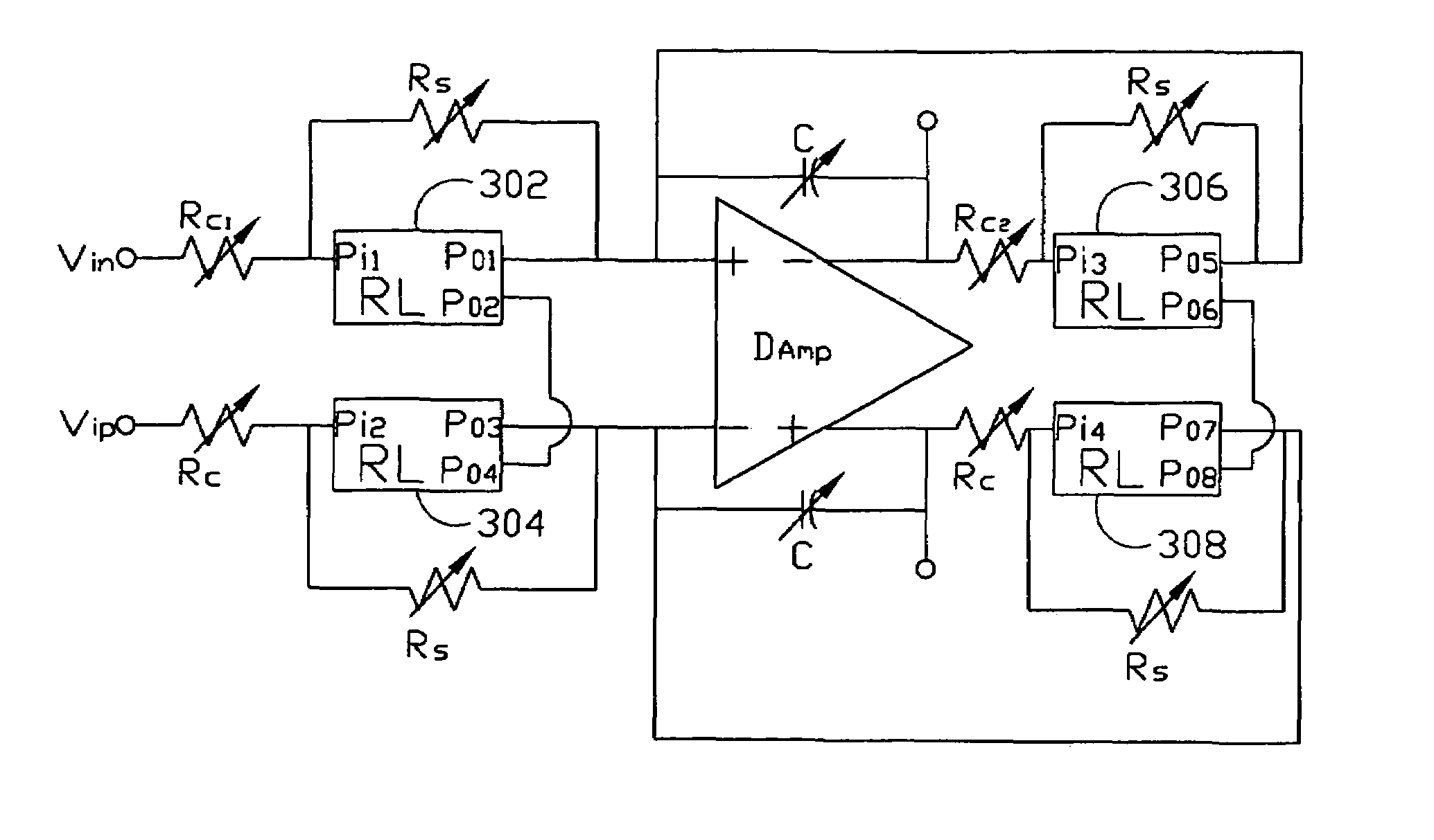
[0022]FIG. 3 depicts an improved active filter circuit according to the present invention. The circuit is composed of a differential amplifier DAmp with two input terminals and two output terminals, which are respectively connected to the four controllable shunt devices 302, 304, 306 and 308 (for instance, resistor ladders, RL); and two identical capacitance component Cf, wherein each of the switch devices respectively used in controllable shunt devices 302, 304, 306 and 308 are exactly the same. The voltage signal inputted from the input terminals of the filter can be transformed into a curre...


PUM


Abstract

A programmable / tunable active low-pass filter at least has the resistors, capacitors and shunt control means. It uses the resistor ladder that is structured with various fixed resistors to implement the shunt control means. The cut-off frequency of a filter is associated with the time constant, which is determined by equivalent resistance and equivalent capacitance value in the filter circuit; therefore, the filter of the present invention allowed users to fine tune the cut-off frequency linearly through the shunt control means when the variation of the environment or process parameters of manufacture cause the cut-off frequency drift, thus, the cut-off frequency can be kept in a constant value. The present invention also provides a means for programming the cut-off frequency to a desirous frequency value dependent upon the conditions of application within a big range. Thus, it can be used in many purposes widely with the same filter circuit.

Description

BACKGROUND OF THE PRESENT INVENTION[0001]1. Field of the Invention[0002]The invention generally relates to analog filter circuits, and more particularly to a method and apparatus for fine tuning and adjusting the cut-off frequency and voltage gain of an active filter.[0003]2. Description of the Prior Art[0004]A filter is an important and familiar component in signal processing systems; and the purpose of the filter is to eliminate the band signals unwanted for retaining and amplifying the band signals desired. Integrating the filters into one chip is a common trend in the manufacture process of the advanced integrated circuit, especially to the communication markets. As the communication system continuously develops, the signal-processing circuits not only require high performances, but also should have a multi-function for a system to process different types of signals. For instance, the 2nd / 3rd generation cell phone in wireless communication and V / ADSL (i.e. very high data / asymmet...

Claims


Application Information

Patent Timeline
Patent Type & Authority Patents(United States)
IPC IPC(8): H03K5/00H03H1/02H03H11/12H03L7/00
CPCH03H11/1291H03H1/02
Inventor LOU, CHIH-HONGCHEN, HUNG-I
Owner IND TECH RES INST
Why Eureka
Try Eureka