Liquid crystal display with mirror mode having top reflective polarizer

a liquid crystal display and mirror mode technology, applied in the direction of polarising elements, display means, instruments, etc., can solve the problems of reducing contrast, deteriorating viewing angle properties, blurred display images, etc., to avoid degraded display quality, enhance shock resistance of display devices, and improve display quality

Inactive Publication Date: 2006-06-06
BOE TECH GRP CO LTD
View PDF31 Cites 224 Cited by
  • Summary
  • Abstract
  • Description
  • Claims
  • Application Information

AI Technical Summary

Benefits of technology

[0053]As the form that the first polarized light selecting unit is fixed to the transparent member, two cases are named: the case where only the first polarized light selecting unit is fixed to the transparent member, and the case where the display unit or the transmitting polarization axis varying unit is fixed along with the first polarized light selecting unit. In the latter case, it is preferable to fix the transparent member via a transparent bonding layer having elasticity. Accordingly, the influence of an external stress (such as shock) on the display unit and the transmitting polarization axis varying unit can be relaxed, and the shock-resistance Of the display device can be enhanced. In addition, this characteristic is similarly applicable to the first and second display devices, considering that the polarized light selecting unit is equivalent to the first polarized light selecting unit.
[0054]Furthermore, the surface of the transparent member on the first polarized light selecting unit is desirably flat. Accordingly, the surface on the backside of the transparent member is made flat. Therefore, the surface on the viewing side of the first polarized light selecting unit closely contacted with the surface can be formed flat. Particularly, the first polarized light selecting unit is available as a sheet material having flexibility. Thus, the surface on the backside of the transparent member is formed flat and the first polarized light selecting unit is closely contacted or bonded to the surface, which allows the first polarized light selecting unit to be kept flat. Therefore, the mirror surface state in the mirror mode can be high quality. Furthermore, this characteristic is similarly applicable to the first and second display devices, considering that the polarized light selecting unit is equivalent to the first polarized light selecting unit.
[0055]Moreover, the surface on the viewing side of the transparent member is desirably a curved surface. Accordingly, the transparent member can be used as an optical lens, which allows the display screen to be visibly recognized in a properly enlarged or reduced state. This characteristic is similarly applicable to the first and second display devices, considering that the polarized light selecting unit is made equivalent to the first polarized light selecting unit.
[0056]Next, an electronic device of the invention is provided with the display device according to any one of the above. As described above, the display device is configured to be switchable between the display mode and the mirror mode by only disposing the polarized light selecting unit on the viewing side of the display unit. Therefore, degraded display quality can be avoided, and also the electronic device can be reduced in size and weight. Accordingly, the electronic device is preferably configured as portable electronic devices such as a mobile phone and a personal information terminal.
[0057]In addition, another electronic device of the invention has the display device according to any one of the above and a display drive unit adapted to drive the transmitting polarization axis varying unit. The display device is switchable, as described above, between the display mode and the mirror mode without disposing another transmitting polarization axis varying unit on the viewing side. Therefore, display quality in the display mode can be improved. Particularly, the display device can be formed to be low-profile and light-weight, and thus the electronic device is preferably configured as portable electronic devices such as a mobile phone and a personal information terminal.

Problems solved by technology

Therefore, the following problems tend to occur: a reduction in contrast due to the interface reflection in the front and back sides of the display switching part, coloring, the deterioration of the viewing angle property, and a blurred display image due to the optical property of the display switching part.
In any case, in the traditional display device, degraded display quality is inevitable due to the double structure of the display part and the display switching part.
Thus, there is a problem that the device becomes thicker and heavier.
This problem becomes a great disadvantage because portability is impaired, particularly, when the device is mounted in a portable electronic device.
Thus, the specular reflection of the high intensity outside light is difficult to view.

Method used


Image

  • Liquid crystal display with mirror mode having top reflective polarizer
  • Liquid crystal display with mirror mode having top reflective polarizer
  • Liquid crystal display with mirror mode having top reflective polarizer

Examples


first embodiment

[0083

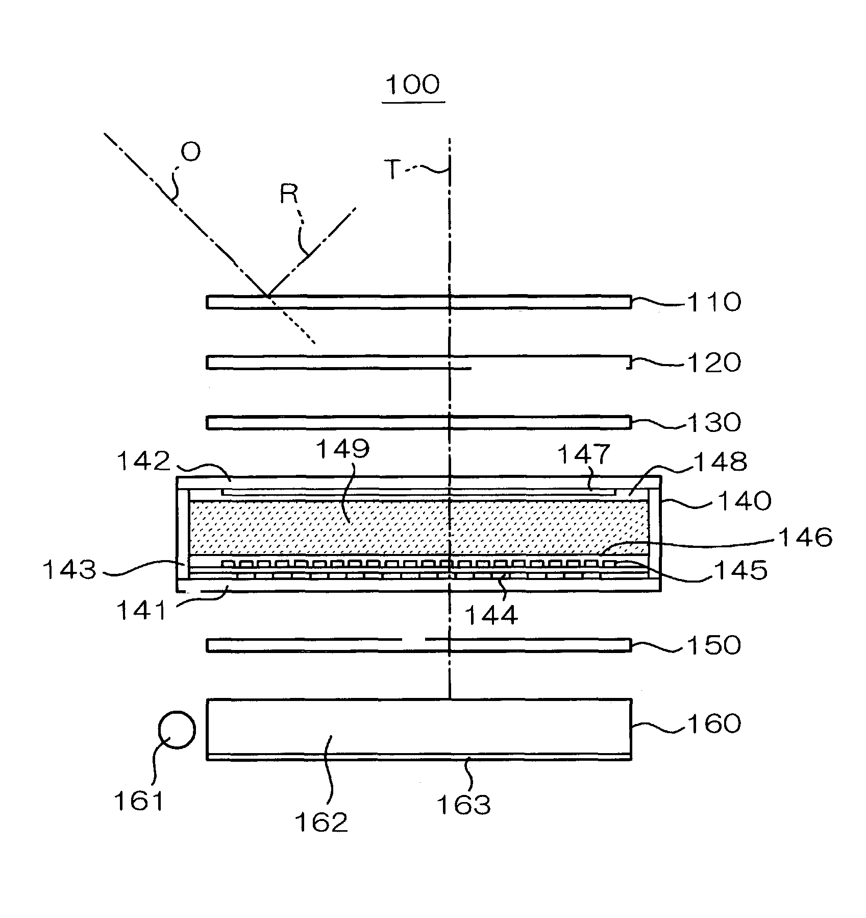
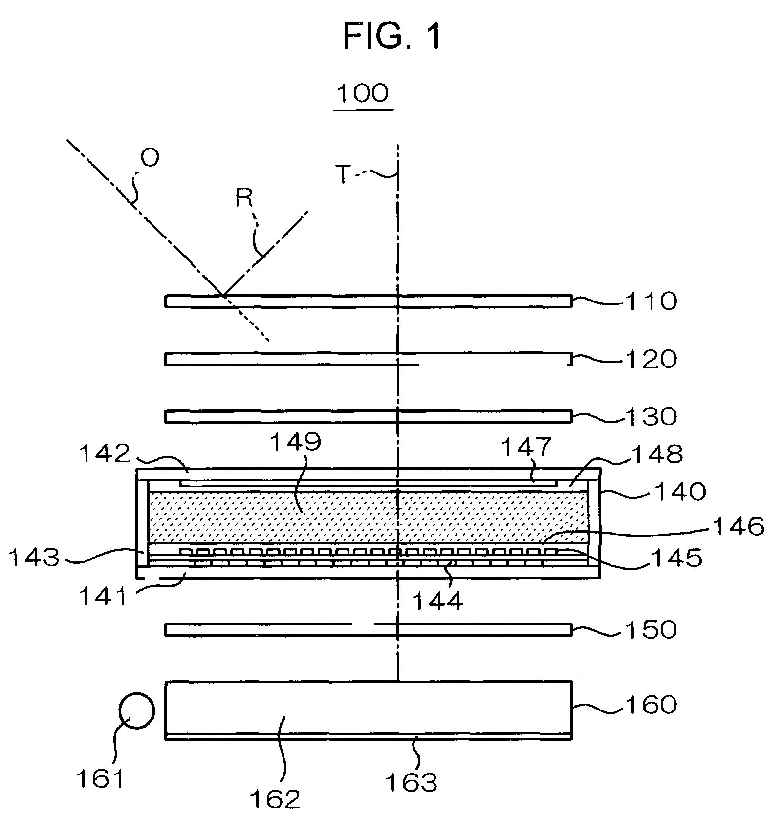
[0084]First, the configuration of a first embodiment in the invention will be described with reference to FIG. 1. In a display device 100 shown in FIG. 1, a reflective polarizer 110, a polarizer 120, a retarder 130, a liquid crystal panel 140, a polarizer 150, and a backlight 160 are sequentially disposed from the viewing side (the upper side in the drawing).

[0085]The reflective polarizer 110 transmits a polarized light component having a vibration plane parallel to the transmitting polarization axis, and reflects a polarized light component having a vibration plane parallel to the direction crossing (preferably orthogonal) the transmitting polarization axis. As the reflective polarizer, a multilayer product having birefringent polymer films different from each other laminated, that is the multilayer product described in PCT / A / WO95 / 27919, or a product having quarter (¼) wavelength plates disposed on the front and back sides of a cholestric liquid crystals can be used. As the mu...

second embodiment

[0107

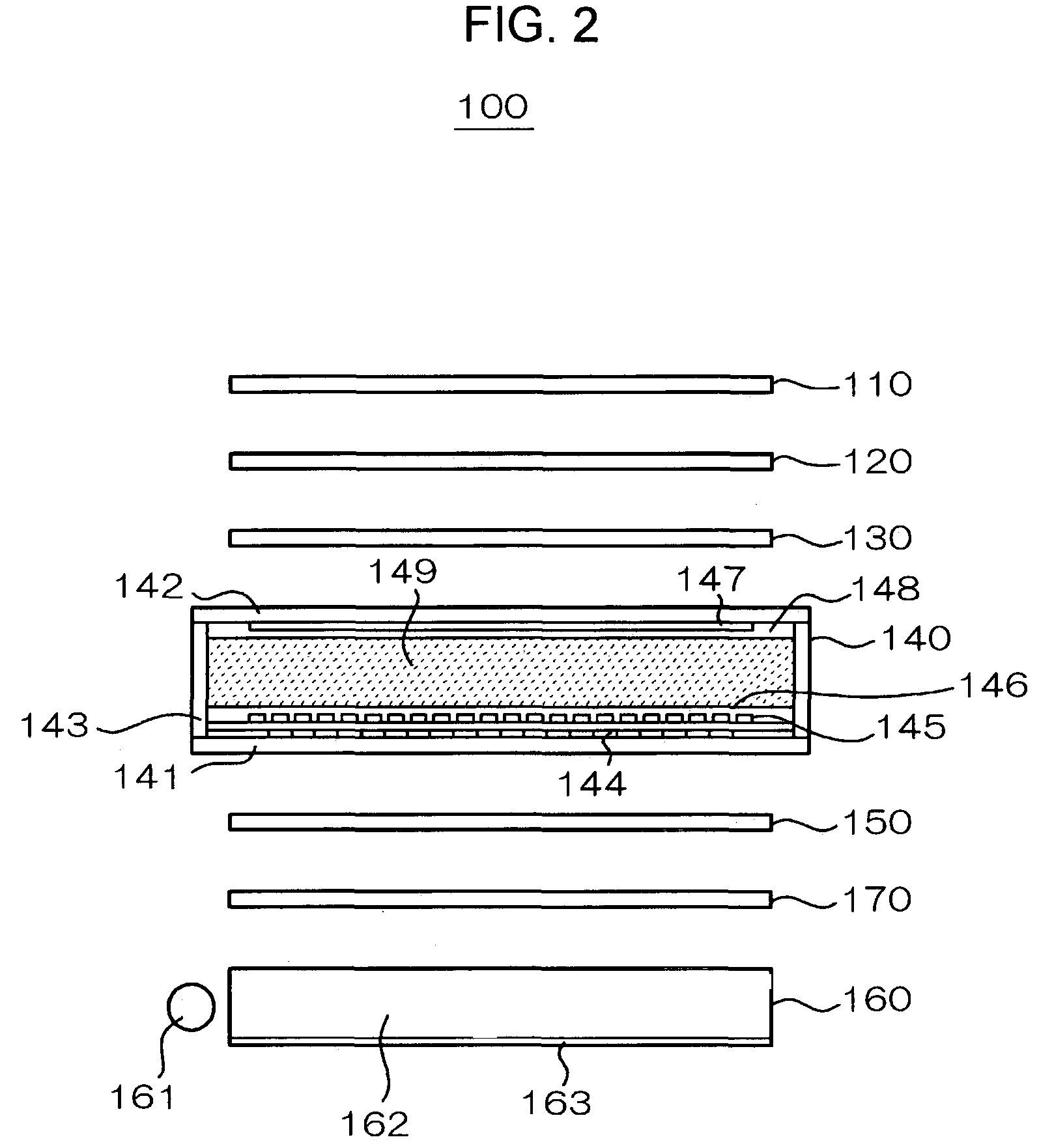
[0108]Next, a second embodiment of the invention will be described with reference to FIG. 2. In this embodiment, the same components as the first embodiment are designated the same numerals and signs, and the description for them is omitted. In the embodiment, a reflective polarizer 110, a polarizer 120, a retarder 130, a liquid crystal panel 140, a polarizer 150, and a backlight 160 are sequentially disposed from the viewing side. The different point from the first embodiment is in that a reflective polarizer 170 is further disposed between the polarizer 150 and the backlight 160. This reflective polarizer 170 is the same as the reflective polarizer 110, but its transmitting polarization axis is disposed in the attitude matched with the transmitting polarization axis of the polarizer 150.

[0109]In the embodiment, the reflective polarizer 170 reflects the polarized light component of the luminous light emitted from the backlight 160, which does not pass through the polarizer 150...

third embodiment

[0111

[0112]Next, a third embodiment of the invention will be described with reference to FIG. 3. In this embodiment, the same components as the second embodiment are designated the same numerals and signs, and the description for them is omitted. In the embodiment, a reflective polarizer 110, a polarizer. 120, a retarder 130, a liquid crystal panel 140, a polarizer 150, a reflective polarizer 170, and a backlight 160 are disposed sequentially from the viewing side. A transparent protective film 111 is further formed on the surface on the viewing side of the reflective polarizer 110.

[0113]The protective film 11 can be formed of a thin film such as acryl resin, SiO2 TiO2. Particularly, it is preferably a hard protective film having a hardness equal to or greater than inorganic glass such as SiO2 and TiO2. It is acceptable that the protective film is a product bonded with a film or sheet formed of a transparent material, or a product directly deposited on the surface of the reflective ...


PUM

PropertyMeasurementUnit
emission angleaaaaaaaaaa
twisted angleaaaaaaaaaa

Abstract

In a display device 100, a reflective polarizer 110, a polarizer 120, a retarder 130, a liquid crystal panel 140, a polarizer 150, and a backlight 160 are disposed sequentially from the viewing side. When the liquid crystal panel 140 is set in a light blocking state or the backlight 160 is set in an unlit state, the reflection of an outside light “O” turns the display screen into a mirror state. When the backlight 160 is set in a lit state to drive the liquid crystal panel 140, a transmitted light “T” allows a particular display screen to be visually recognized.

Description

BACKGROUND OF THE INVENTION[0001]1. Field of the Invention[0002]The present invention relates to a display device and an electronic device having the same, and more particularly to a configuration suitable for a display capable of switching a display screen between a display mode and a mirror mode.[0003]2. Related Art[0004]Traditionally, a display device has been known in which two liquid crystal panels are overlaid to switch between the display mode to perform normal display and the mirror mode to change the whole piece into a mirror surface state. For example, there is a display device in which a display switching part is disposed on the viewing side of a display part having the same structure as the general liquid crystal display device and the display switching part is disposed with a reflective type polarizer, a liquid crystal panel and an absorption type polarizer sequentially from the display part side to the viewing side. In this display device, the reflective type polarizer...

Claims


Application Information

Patent Timeline
Patent Type & Authority Patents(United States)
IPC IPC(8): G02F1/1335G02B5/30G02F1/13G02F1/1333G02F1/13357G02F1/13363G09F13/12H04M1/02
CPCG02F1/133528H04M1/0266G09F13/12G02F2001/133545G02F2001/133562G02F2203/02H04M1/0202G02F2001/133626G02F1/133545G02F1/133562G02F1/133626
Inventor HINATA, SHOJIMAEDA, TSUYOSHI
Owner BOE TECH GRP CO LTD
Why Eureka
Try Eureka