Acoustic measurement method and apparatus

a measurement method and acoustic technology, applied in the field of soundintensity vector measurement, can solve problems such as less stable, achieve the effects of preserving the ommidirectional nature of the probe, compact and accurate, and reducing interference with the sound field

Inactive Publication Date: 2006-06-06
HICKLING ROBERT
View PDF4 Cites 32 Cited by
  • Summary
  • Abstract
  • Description
  • Claims
  • Application Information

AI Technical Summary

Benefits of technology

[0031]Measurement accuracy is ensured by a novel normalization and calibration procedure to make the sensitivity of the probe omnidirectional by making the frequency responses of the four microphones appear identical in the signal processor. The procedure also makes the signals from the microphones in the probe more accurate.
[0032]Also, in accordance with another aspect of the invention, it is possible to perform accurate measurements over a broader frequency range than before, with a nested set of two or more tetrahedral arrangements with different spacing d, having the same orientation and measurement point.
[0033]Yet another feature is that the sound-intensity vector provides a compact and accurate way of determining the direction of a sound source in air. This can be displayed on a monitor screen in the form of an easily understood elevation-azimuth plot or other suitable representation. Elevation-azimuth plots were used by Hickling et al. Other representations were used by Segiguchi et al and by P. Rasmussen. The practicality of the elevation-azimuth representation can be demonstrated by a suitable holder for the sound-intensity probe. With this holder the elevation and azimuth of the probe can be adjusted either by hand or by remote digital control, so that it points at a sound source. Direction can then be indicated by laser pointers attached to the holder. Finding the direction to a noise source at a known location is the only way of checking the accuracy of the sound-intensity vector.
[0034]Another feature of the holder is that the narrow leads from the four microphones are routed so as to reduce interference with the sound field, thus helping to preserve the ommidirectional nature of the probe. This can be accomplished, by laying a lead along a radial spoke of the holder and thence around the outer frame to the handle and the digital signal processor. The handle of the holder can contain batteries for the laser pointers.

Problems solved by technology

Their only drawback appears to be that they are less stable.

Method used


Image

  • Acoustic measurement method and apparatus
  • Acoustic measurement method and apparatus
  • Acoustic measurement method and apparatus

Examples


Embodiment Construction

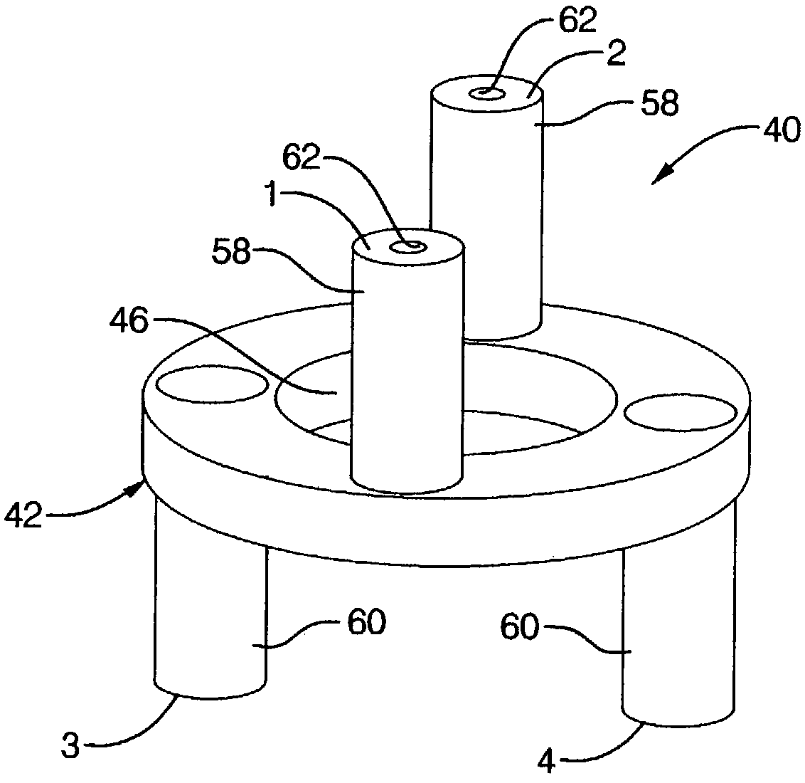
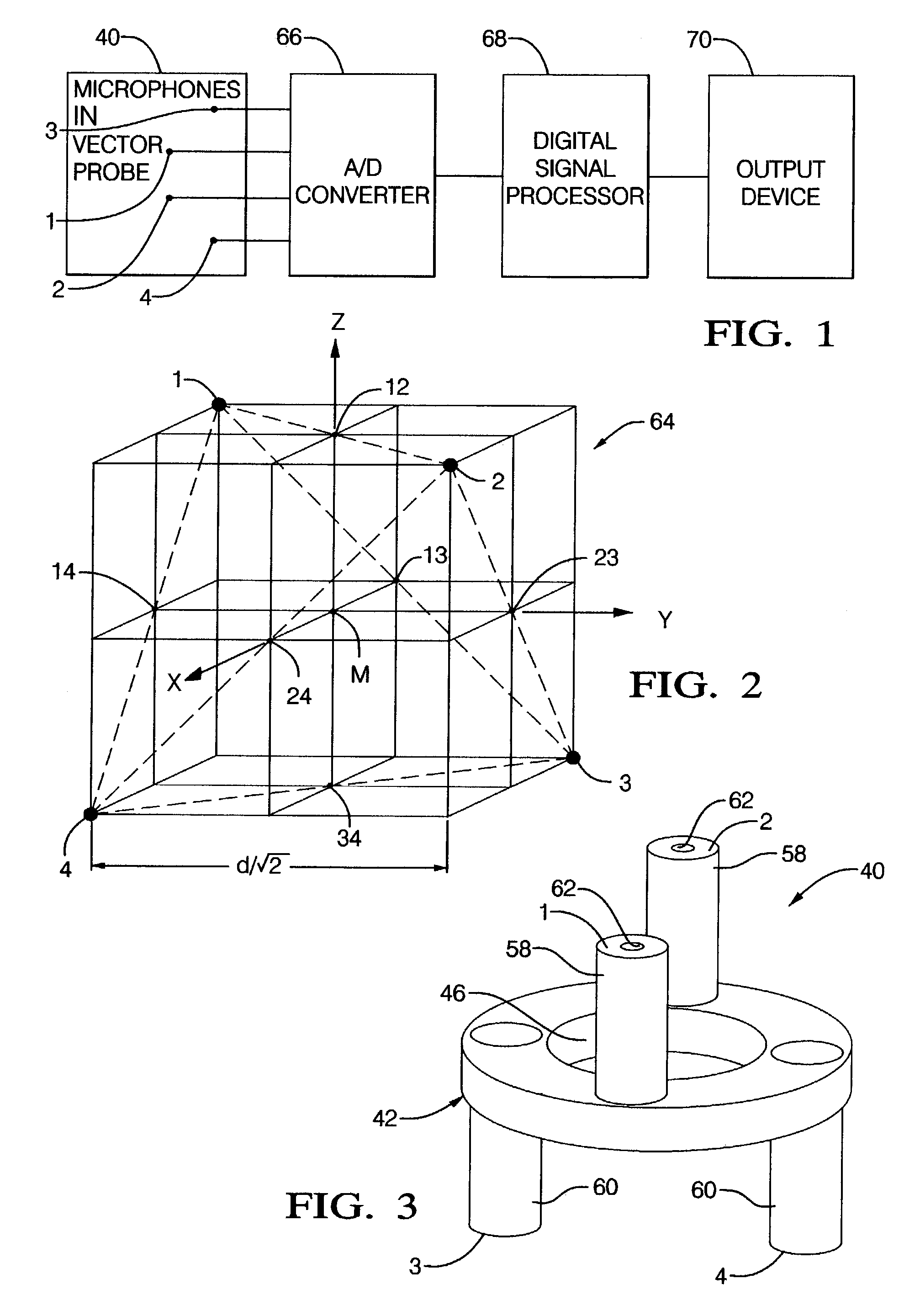
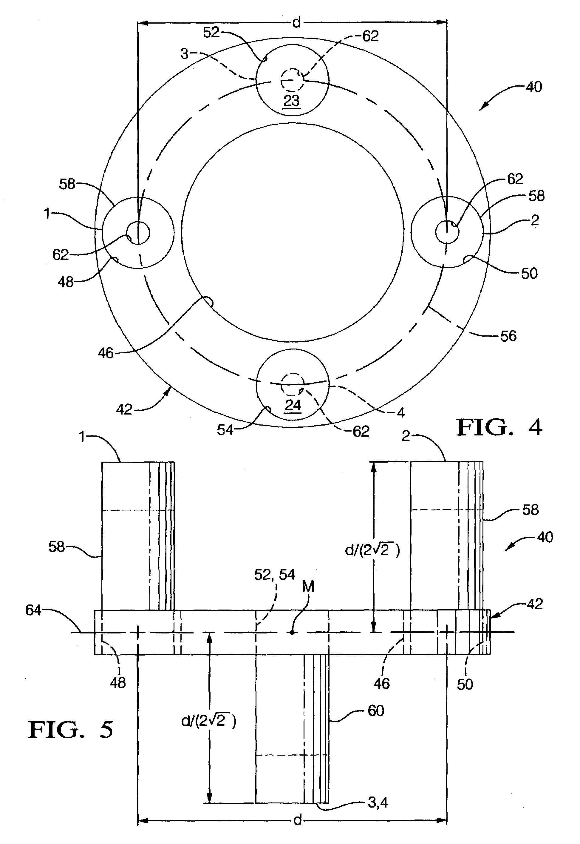
[0050]FIG. 1 is a block diagram illustrating the acoustic measurement apparatus of the present invention. Block 40 represents the vector probe 40 carrying microphones 1, 2, 3 and 4. The four microphones are connected to a converter 66 that converts the analog signals from the microphones to digital form for input to a digital signal processor 68. The processor normalizes the digitized signals using transfer functions determined using a novel technique to be described later. At the measurement point, it computes the three components of the sound-intensity vector and, additionally, the three components of the sound-velocity vector and the sound pressure, using mathematical relations to be subsequently discussed, and presents the results on a monitor screen or other output device indicated by numeral 70. The invention uses a cross-spectral formulation, to be subsequently described, to determine sound intensity. The signal processor can also determine the direction of a sound source fro...


PUM

PropertyMeasurementUnit
sizesaaaaaaaaaa
sizesaaaaaaaaaa
diameteraaaaaaaaaa

Abstract

Method and apparatus for simultaneous acoustic measurement at a point (M) in space of the three components of the sound intensity vector. A preferred omnidirectional vector probe (40) includes a central ring (42) with four small, microphones on tubes attached to the ring spaced from one another in a regular tetrahedral arrangement. The tubes are parallel to the axis of the ring, two on one side (58) and two on the reverse side (60) of the ring, with two of the microphones pointing in one direction and two in the opposite direction. The microphone signals are processed by an analog-to-digital converter feeding a digital signal processor (68) and employing a cross-spectral formulation to compute a sound intensity vector at the measurement point (M). Sound velocity and pressure can also be determined at this point. The resulting data may be outputted on a computer screen or other device (70). Additional related features and methods are disclosed.

Description

TECHNICAL FIELD[0001]This invention relates to the measurement of the sound-intensity vector and, more particularly, to methods and means of performing such measurement with four small microphones.BACKGROUND OF THE INVENTIONPrevious Attempts to Measure the Sound-Intensity Vector[0002]The sound-intensity vector, or sound power flow per unit area, is defined as the product of sound pressure and sound velocity. It is difficult to measure as a function of time and is usually determined as a function of frequency. Ways of measuring sound intensity are described in[0003]1. F. J. Fahy, 1995, “Sound Intensity”, Second Edition, E& FN Spon, An imprint of Chapman and Hall, London.[0004]2. Anon., 1996, “Instruments for Measurement of Sound Intensity”, Standard ANSI S1.9-1996, American National Standards Inst.Sound intensity is not measured directly. It involves the use of a measurement calculation. Generally only one component of the intensity vector is measured using a pair of microphones. Two...

Claims


Application Information

Patent Timeline
Patent Type & Authority Patents(United States)
IPC IPC(8): H04R3/00G01H3/00G01H3/12G01N29/00G01N29/11G01N29/34G01N29/36G01S3/80G01V1/00G01V1/16
CPCG01H3/00G01H3/125G01N29/11G01N29/341G01V1/16G01V1/003G01N29/36G01N2291/02491G01N2291/02836G01N2291/044
Inventor HICKLING, ROBERT
Owner HICKLING ROBERT
Why Eureka
Try Eureka