Structure of an oil-free compressor on a vehicle

a technology of oil-free compressor and vehicle, which is applied in the direction of positive displacement liquid engine, piston pump, liquid fuel engine, etc., can solve the problems of increased increased heat development, and oil fouling of pneumatically operated brake unit on the vehicle, so as to achieve sufficient cooling effect, increase maintenance and disposal expenditure, and high heat development

Inactive Publication Date: 2006-06-13
KNORR BREMSE SYST FUR SCHIENENFAHRZEUGE GMBH
View PDF11 Cites 13 Cited by
  • Summary
  • Abstract
  • Description
  • Claims
  • Application Information

AI Technical Summary

Benefits of technology

[0003]The compressors used in the vehicle field are normally subjected to a long continuous operation or to a frequent switching-on and switching-off, which, as a result of friction, leads to a high heat development. Therefore, in the past, compressors that were predominantly used in the vehicle field ensured a sufficient cooling effect on the basis of oil lubrication. However, oil lubrication carries the risk that the lubricating oil, situated in the housing of the compressor unit, in the case of the piston compressor, would penetrates through the piston-cylinder pairing into the pneumatic system, which may result in a fouling by oil of pneumatically operated brake units on the vehicle. Furthermore, the condensate, which occurs during the required air drying of the pneumatic system, because of its oil content, has to be collected for environmental protection reasons in heatable containers and has to be drained and disposed of at regular intervals. This leads to increased maintenance and disposal expenditures as well as to a high oil consumption. Added to the above are difficulties with emulsion formations in the oil circuit of these oil-lubricated compressor units which frequently occur in the case of a low switch-on duration in the winter operation.
[0004]Recently, dry-running compressors have therefore been increasingly used. A dry-running compressor operates in its compressor unit without a lubricating oil situated in the housing, that is, oil-free. Instead, in the case of a piston compressor, the lubrication on the piston travel path is replaced by a particularly low-friction dynamic sealing arrangement. All rotating components are normally disposed in roller bearings. The encapsulated roller bearings are provided with a temperature-stable long-lived grease filling. In the valve area, slidably guided components are largely avoided. Because of these measures, an oil lubrication will not be required in the compressor unit. The risk of a foiling by oil of the generated compressed air can therefore be excluded. As a result of the elimination of an oil circuit, the oil-free compressor can, in addition, have a relatively light construction.

Problems solved by technology

The compressors used in the vehicle field are normally subjected to a long continuous operation or to a frequent switching-on and switching-off, which, as a result of friction, leads to a high heat development.
However, oil lubrication carries the risk that the lubricating oil, situated in the housing of the compressor unit, in the case of the piston compressor, would penetrates through the piston-cylinder pairing into the pneumatic system, which may result in a fouling by oil of pneumatically operated brake units on the vehicle.
This leads to increased maintenance and disposal expenditures as well as to a high oil consumption.
Added to the above are difficulties with emulsion formations in the oil circuit of these oil-lubricated compressor units which frequently occur in the case of a low switch-on duration in the winter operation.
Because of the light-construction trend, which is increasing in the vehicle field, light carrier structures are increasingly used also for frame constructions, which carrier structures, however, frequently have a number of unfavorable natural frequencies, which are close to the rotational speed of the compressor of the pneumatic system which is arranged thereon.
It therefore presents considerable problems to sufficiently observe the required specifications concerning permissible structure-born noise levels.
Having the compressor arranged essentially vertical with respect to the vehicle floor results in a particularly low-vibration arrangement of the compressor on the vehicle.
By this arrangement in the interior of the vehicle, little floor surface of the vehicle is needed, which permits a considerable saving of space with respect to the limited floor surface.

Method used


Image

  • Structure of an oil-free compressor on a vehicle
  • Structure of an oil-free compressor on a vehicle
  • Structure of an oil-free compressor on a vehicle

Examples


Embodiment Construction

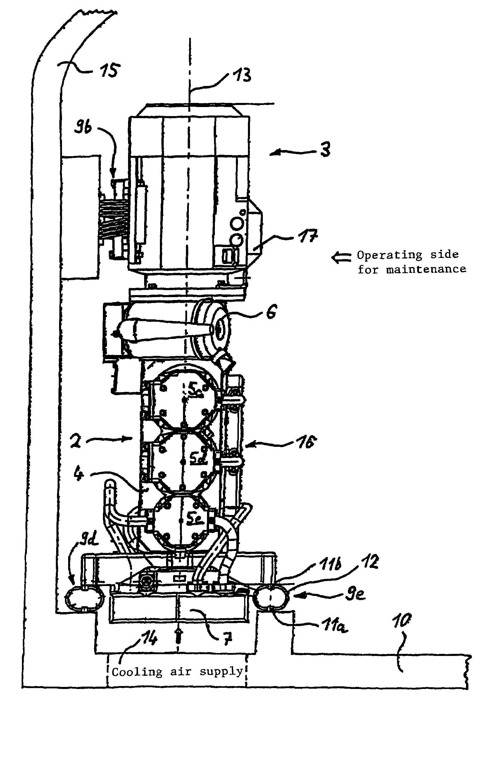
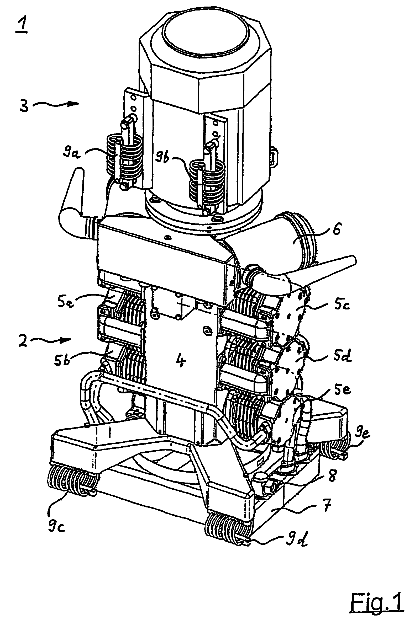
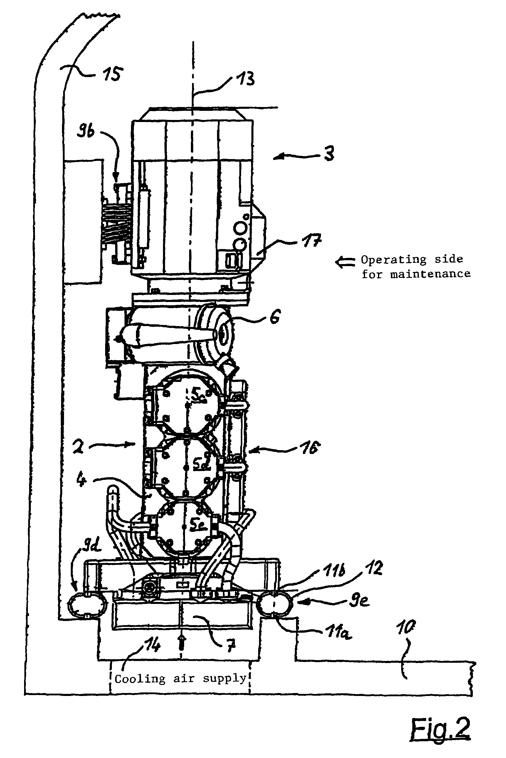
[0017]The oil-free compressor 1 according to FIG. 1 includes a compressor unit 2 with a coaxially flanged-on driving unit 3. The driving unit 3 is constructed as an electric motor and is detachably fastened to a housing 4 of the compressor unit 2 by a screwed connection (not shown). The driving unit 3 causes rotational movement of a crankshaft (not shown) arranged in the housing 4, which rotational movement is converted to a stroke movement for pistons 5 (not shown) which are housed inside pot-shaped cylinders 5a to 5e fastened on the housing 4 for generating compressed air. By the piston 5 movement, air is taken in from the atmosphere by an inlet-side air filter 6 and is compressed. The thus generated compressed air passes through a cooler unit 7 having a propeller (not shown) and the compressed air will then be available to the pneumatic system of a vehicle by connection 8. In this embodiment, the compressor unit 2 is constructed as a multi-stage piston compressor with a low-press...


PUM


Abstract

An arrangement of an oil-free compressor apparatus on a rail vehicle for supplying compressed air to pneumatic units assigned to the rail vehicle. The arrangement includes an oil-free compressor and a cooler unit connected with the compressor. The arrangement also includes a rail vehicle having a floor with at least one opening. The compressor is fastened on at least one side to the vehicle floor such that a main axis of rotation of the compressor is arranged essentially vertical with respect to the vehicle floor. The cooler unit interacts with the at least one opening that is configured to take in cooling air to cool the compressor.

Description

BACKGROUND AND SUMMARY OF THE INVENTION[0001]The present invention relates to an arrangement of an oil-free compressor on a vehicle, particularly on a rail vehicle, for supplying compressed air to various pneumatic units assigned to the vehicle.[0002]Normally, a pneumatic system is provided for a rail vehicle, by which the brakes of the rail vehicle, as essential pneumatic units, are operated. For supplying the compressed air, a compressor is used which is usually arranged on the outside of the rail vehicle and in the area of the vehicle floor along the length in a horizontally hanging or standing manner. The compressor consists of a driving unit, which generates a rotating movement and is normally constructed as an electric motor, and of a compressor unit, which essentially consists of several pot-type cylinders for interior pistons, which are arranged on a housing for a crankshaft. The crankshaft is driven by the driving unit converting its rotating movement by one connecting rod ...

Claims


Application Information

Patent Timeline
Patent Type & Authority Patents(United States)
IPC IPC(8): F04B39/00F04B17/00B61C3/00B61C1/00B60T17/00B60T17/02B61C17/00
CPCB60T17/008B60T17/02B61C17/00
Inventor HARTL, MICHAELMEYER, FRANK
Owner KNORR BREMSE SYST FUR SCHIENENFAHRZEUGE GMBH
Why Eureka
Try Eureka