Active vibration suppression apparatus, control method therefor, and exposure apparatus having active vibration suppression apparatus

a technology of active vibration suppression and control method, which is applied in the direction of photomechanical apparatus, shock absorbers, instruments, etc., can solve the problems of preventing the attainment of sufficient vibration suppressing effect, mass and movable stroke sufficient to achieve a predetermined vibration suppressing action, and severe requirements for vibration reduction/suppression performance, etc., to reduce the vibration of the surface plate

Inactive Publication Date: 2006-06-20
CANON KK
View PDF11 Cites 24 Cited by
  • Summary
  • Abstract
  • Description
  • Claims
  • Application Information

AI Technical Summary

Benefits of technology

[0067]According to the present invention, there is provided a maintenance method for an exposure apparatus, the maintenance method comprising: the step of causing a vendor or user of the exposure apparatus to provide a maintenance database connected to an external network of the semiconductor manufacturing factory; the step of allowing access from the semiconductor manufacturing factory to the maintenance database via the external network; and the step of transmitting maintenance information accumulated in the maintenance database to the semiconductor manufacturing factory via the external network, and maintaining the exposure apparatus on the basis of the maintenance information, wherein the exposure apparatus includes a stage apparatus having a substrate or master plate as an exposure target mounted thereon and performing precision positioning operation, and an active vibration suppression apparatus which acts on a surface plate on which the stage apparatus is mounted or on an exposure apparatus housing structure mounted on the surface plate to reduce vibrations of the surface plate or the exposure apparatus housing structure in a translation direction, which are produced upon driving of the stage apparatus, the active vibration suppression apparatus includes an actuator which is fixed to the surface plate or the exposure apparatus housing structure and generates a thrust, an inertial load which is connected to the actuator and is driven relative to the surface plate or the exposure apparatus housing structure in accordance with the thrust generated by the actuator, and a driving circuit for generating a driving command signal for controlling driving of the inertial load and driving the actuator in accordance with the driving command signal, and wherein the actuator drives the inertial load with the generated thrust, and applies a drive reaction force generated upon driving of the inertial load as a control force to the surface plate or the exposure apparatus housing structure to reduce vibrations produced in the surface plate or the exposure apparatus housing structure.
[0068]According to the present invention, there is provided a maintenance method for an exposure apparatus, the maintenance method comprising: the step of causing a vendor or user of the exposure apparatus to provide a maintenance database connected to an external network of the semiconductor manufacturing factory; the step of allowing access from the semiconductor manufacturing factory to the maintenance database via the external network; and the step of transmitting maintenance information accumulated in the maintenance database to the semiconductor manufacturing factory via the external network, and maintaining the exposure apparatus on the basis of the maintenance information, wherein the exposure apparatus includes a stage apparatus having a substrate or master plate as an exposure target mounted thereon and performing precision positioning operation, and an active vibration suppression apparatus which acts on a surface plate on which the stage apparatus is mounted or an exposure apparatus housing structure mounted on the surface plate to reduce vibrations of the surface plate or the exposure apparatus housing structure in a rotational direction which are produced upon driving of the stage apparatus, the active vibration suppression apparatus including a rotating actuator which is fixed to the surface plate or the exposure apparatus housing structure and generates a torque in a rotational direction, an inertial load which is connected to the actuator and moves in the rotational direction relative to the surface plate or the exposure apparatus housing structure in accordance with a torque of the actuator, and a driving circuit for generating a driving command signal for controlling the inertial load and driving the rotating actuator in accordance with the driving command signal, and wherein the rotating actuator rotates / drives the inertial load with a generated torque, and reduces vibrations produced in the surface plate or the exposure apparatus housing structure by applying a drive reaction force generated upon rotating / driving the inertial load as a control torque to the surface plate or the exposure apparatus housing structure.

Problems solved by technology

In a scan exposure apparatus, in particular, since exposure is performed while an exposure stage apparatus performs a scanning operation, severe requirements are imposed on vibration reduction / suppression performance.
However, since an allowable space is limited, a mass and movable stroke sufficient to obtain a predetermined vibration suppressing action and effect may not be ensured.
If the stroke of the inertial load is limited due to such restrictions on the specifications of the structure of the vibration suppression apparatus, the generation of vibrations of frequency components other than the control target, or the like, may prevent a sufficient vibration suppressing effect from being obtained.
This may create a large shock to the vibration suppression control system, resulting in a control operation failure.
In contrast to this, if the control gain is suppressed to prevent an inconvenience caused by stroke over, a necessary control effect cannot be ensured.
In many cases, in an actual apparatus, however, structural resonance vibrations are produced in mounted equipment and structures due to various restrictions on equipment design, and a satisfactory damping property cannot be provided for the resonance vibrations.
In addition, when heavy equipment and structures are fastened to the vibration isolation base or surface plate, a spring / mass system may be formed due to insufficient fastening rigidity, and vibrations may be produced at a level that cannot be neglected in ensuring satisfactory apparatus performance.
When such vibrations are produced in a mounted equipment and structures, even if the vibrations of the vibration isolation base or surface plate are reduced / suppressed, those of these equipment and structures cannot be sufficiently suppressed.
This affects the precision of the apparatus and degrades the exposure performance.
In a semiconductor exposure apparatus, in particular, some structure needs to have a cantilever support structure in terms of equipment layout design, and swinging vibrations are produced around the fulcrum of the structure, affecting the performance of the semiconductor exposure apparatus.
However, such a member cannot be attached because of restrictions on the equipment layout design in many cases.
For this reason, vibrations such as structural resonance of equipment / structure cannot be sufficiently suppressed, and such vibrations often become big factors that hinder an improvement in the performance of a semiconductor exposure apparatus.
For this reason, owing to various uncertainties acting in an apparatus mount environment, unpredictable, uncertain signals may be fed forward to the control system.
That is, this control method has a weak point in the reliability of vibration control operation.
Basically, however, such references are limited to the disclosure of vibration suppression methods and apparatuses aimed at suppressing rigid-body vibrations such as the vibrations of a vibration isolation base or surface plate as a part of an exposure apparatus body.

Method used


Image

  • Active vibration suppression apparatus, control method therefor, and exposure apparatus having active vibration suppression apparatus
  • Active vibration suppression apparatus, control method therefor, and exposure apparatus having active vibration suppression apparatus
  • Active vibration suppression apparatus, control method therefor, and exposure apparatus having active vibration suppression apparatus

Examples


first embodiment

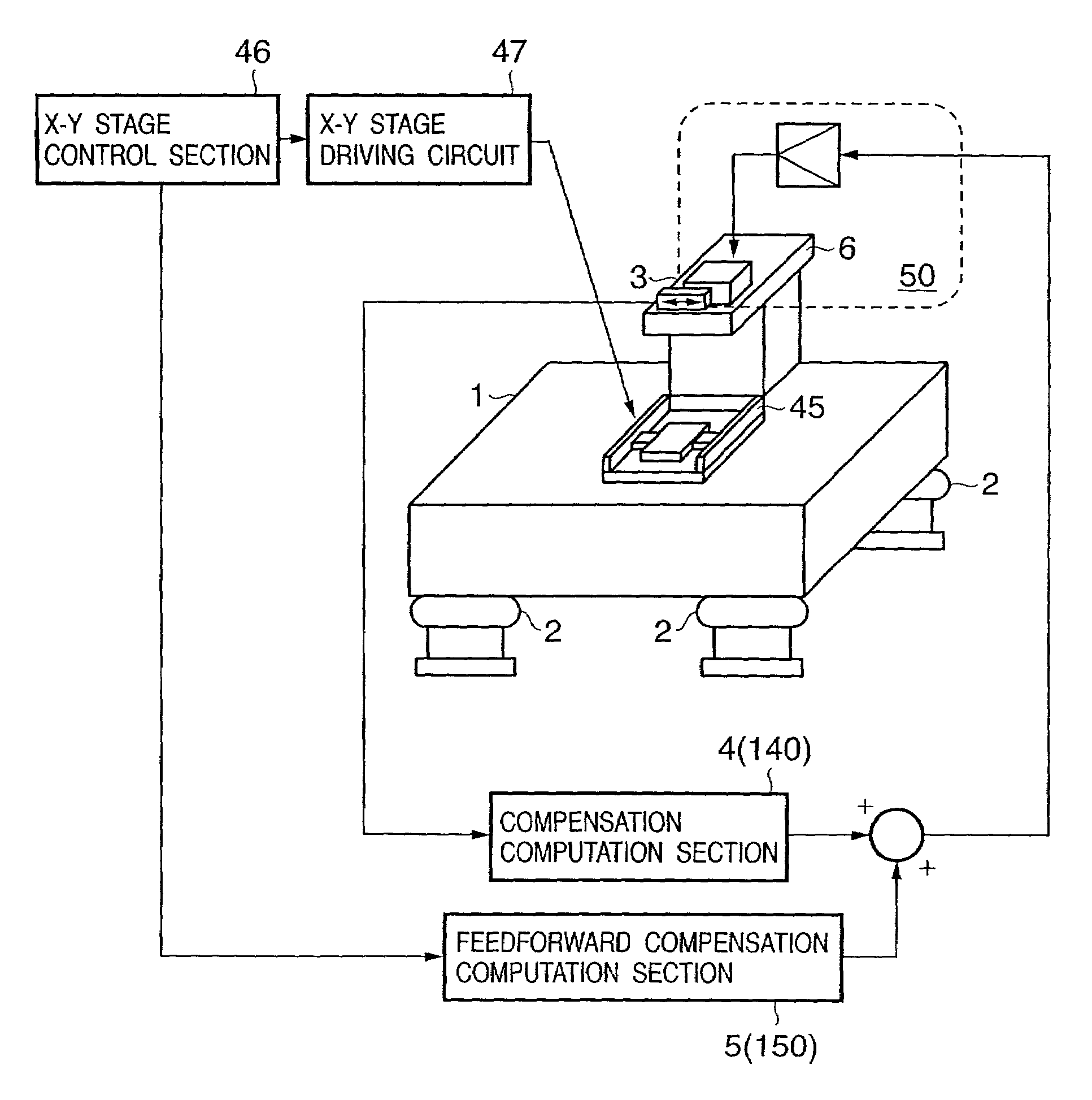
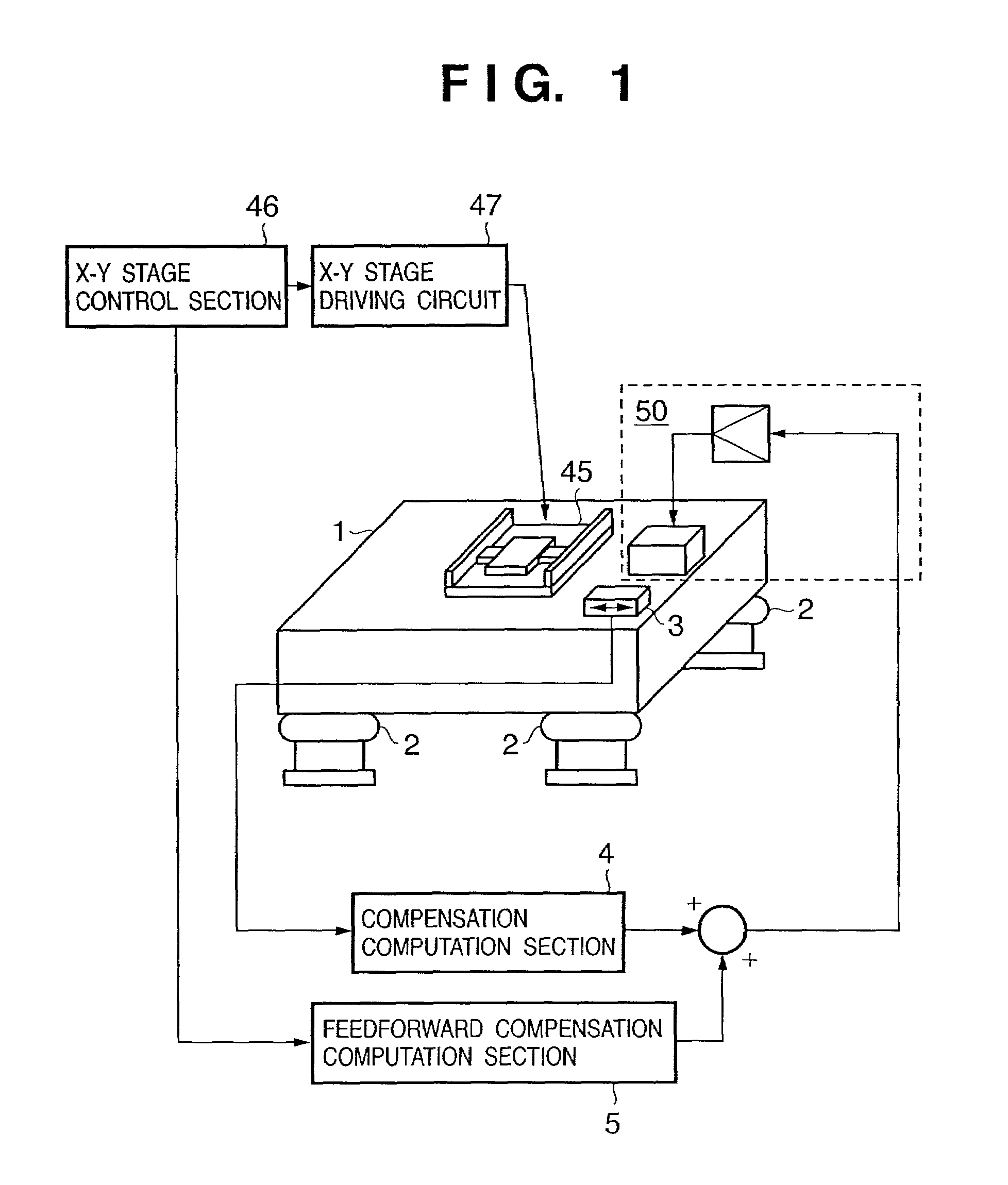
[0097]In the first embodiment of the present invention, an active vibration suppression apparatus will be described below, which reduces vibrations that are produced in a precision equipment mount vibration isolation base or in an object mounted on a vibration isolation base, and affect precision equipment, such as a semiconductor exposure apparatus.

[0098]FIG. 1 is a view showing the arrangement of an active vibration isolation apparatus according to the first embodiment of the present invention. In the active vibration suppression apparatus according to this embodiment, a vibration suppression target is a vibration isolation base 1 supported to be vibration-isolated by support mechanisms 2 such as air springs. In a semiconductor exposure apparatus, an exposure apparatus body supported by a vibration isolation apparatus or a vibration isolation base on which a stage apparatus having a substrate (silicon wafer, or the like) or master plate (reticle, or the like) mounted thereon, and ...

second embodiment

[0134]FIG. 8 is a view showing an example of the arrangement of an apparatus according to the second embodiment of the present invention, which is configured to reduce the vibrations of a structure 6 mounted on a vibration isolation base 1.

[0135]In the first embodiment, the apparatus according to the present invention has been described in detail with reference to the case wherein the vibration isolation base 1 is a vibration suppression target. The second embodiment will exemplify the case wherein local resonance vibrations produced in the structure 6 fastened to the vibration isolation base 1 with relatively high rigidity are reduced / suppressed by an active vibration suppression apparatus according to the present invention. A vibration suppression target in this embodiment is not the natural vibrations of the vibration system constituted by the vibration isolation base 1 and a support mechanism 2, but is the structural resonance vibrations of the structure 6 fastened to the vibrat...

third embodiment

[0148]The third embodiment of the present invention will exemplify the following semiconductor exposure apparatus having the active vibration suppression apparatus shown in FIG. 8 to reduce vibrations that affect the exposure performance.

[0149]In the third embodiment, an apparatus will be described, which has an active vibration suppression apparatus mounted on a structure having a cantilever structure, which is a component of a semiconductor exposure apparatus to reduce / suppress structural vibrations centered on the cantilever fulcrum of the structure. In this case, an embodiment will be described, in which a structure having a cantilever support structure and serving as a vibration suppression target is a mechanical structure as a component of an illumination optical unit for emitting exposure light to expose a silicon wafer as a substrate to a circuit pattern formed on a reticle as a master plate through an optical lens system.

[0150]FIG. 10 is a view showing an embodiment of the ...


PUM

PropertyMeasurementUnit
natural frequencyaaaaaaaaaa
damping propertyaaaaaaaaaa
drive reaction forceaaaaaaaaaa

Abstract

An active vibration suppression apparatus includes an actuator fixed to a vibration suppression target, an inertial load driven relative to the target by the actuator, and a driving system which drives the actuator based on a first signal corresponding to the vibration, generated or to be generated, of the target. The driving system includes a compensation unit which performs a compensation for the first signal. The compensation, separately or as a composite compensation includes (i) a linear compensation for the first signal to obtain a first compensated signal, and (ii) a nonlinear compensation for the first compensated signal to obtain a second compensated signal. A rate of a change in the second compensated signal to a change in an absolute value of the first compensated signal becoming less with an increase of the absolute value.

Description

FIELD OF THE INVENTION[0001]The present invention relates to an active vibration suppression method and apparatus which are suited to realizing the excellent performance of an apparatus by stably and quickly suppressing vibrations such as rigid-body vibrations and structural resonance produced in a structure forming a semiconductor exposure apparatus, an exposure apparatus using the same, and the like.BACKGROUND OF THE INVENTION[0002]With an increase in the precision of a semiconductor exposure apparatus, a vibration isolation / suppression apparatus with higher performance has been required. In a semiconductor exposure apparatus, in particular, it is required to prevent vibrations that affect exposure from being produced in an exposure stage or a structure forming an exposure apparatus body. For this purpose, the exposure apparatus body must be insulated from external vibrations, including vibrations from an apparatus mount pedestal such as a floor, as much as possible, and vibration...

Claims


Application Information

Patent Timeline
Patent Type & Authority Patents(United States)
IPC IPC(8): F16F7/10A47G27/00F16F15/02G03F7/20H01L21/027
CPCG03F7/709F16F7/1005
Inventor MAYAMA, TAKEHIKO
Owner CANON KK
Why Eureka
Try Eureka