Flat-panel display with luminance feedback

a flat-panel display and luminance feedback technology, applied in static indicating devices, television systems, instruments, etc., can solve problems such as poor current control in display devices, degradation of oled luminous efficiency, and low luminous efficiency of oled devices with continuous operation, so as to improve brightness, power consumption, and life. the effect of improving performan

Inactive Publication Date: 2006-06-20
GLOBAL OLED TECH
View PDF33 Cites 206 Cited by
  • Summary
  • Abstract
  • Description
  • Claims
  • Application Information

AI Technical Summary

Benefits of technology

[0011]The advantages of this invention are an emissive digital image display device with improved performance. By integrating light detection capabilities together with feedback logic to control the operational characteristics of the emitters, improved lifetime, brightness, luminous uniformity, and power consumption can all be achieved.

Problems solved by technology

The luminous efficiency of the OLED devices often decreases significantly with continuous operation due to the instability of the organic materials.
This instability may be as a result of aging, temperature changes, humidity, or other environmental stresses.
Thus, a degradation of OLED luminous efficiency means that upon usage more and more current must pass through the OLED in order to achieve the same luminance.
Moreover, current control in a display device is problematic, especially as compared to voltage control, requiring more circuitry and thus increasing the complexity of the supporting electronics within the display.
One problem with these approaches is that the feedback does not directly respond to the emissivity of the pixels themselves, or address problems with different types (e.g. colors) of pixels within a display.
This approach has the problem that the sensor device obscures the display during the calibration and is not capable of providing real time operation.

Method used


Image

  • Flat-panel display with luminance feedback
  • Flat-panel display with luminance feedback
  • Flat-panel display with luminance feedback

Examples


Embodiment Construction

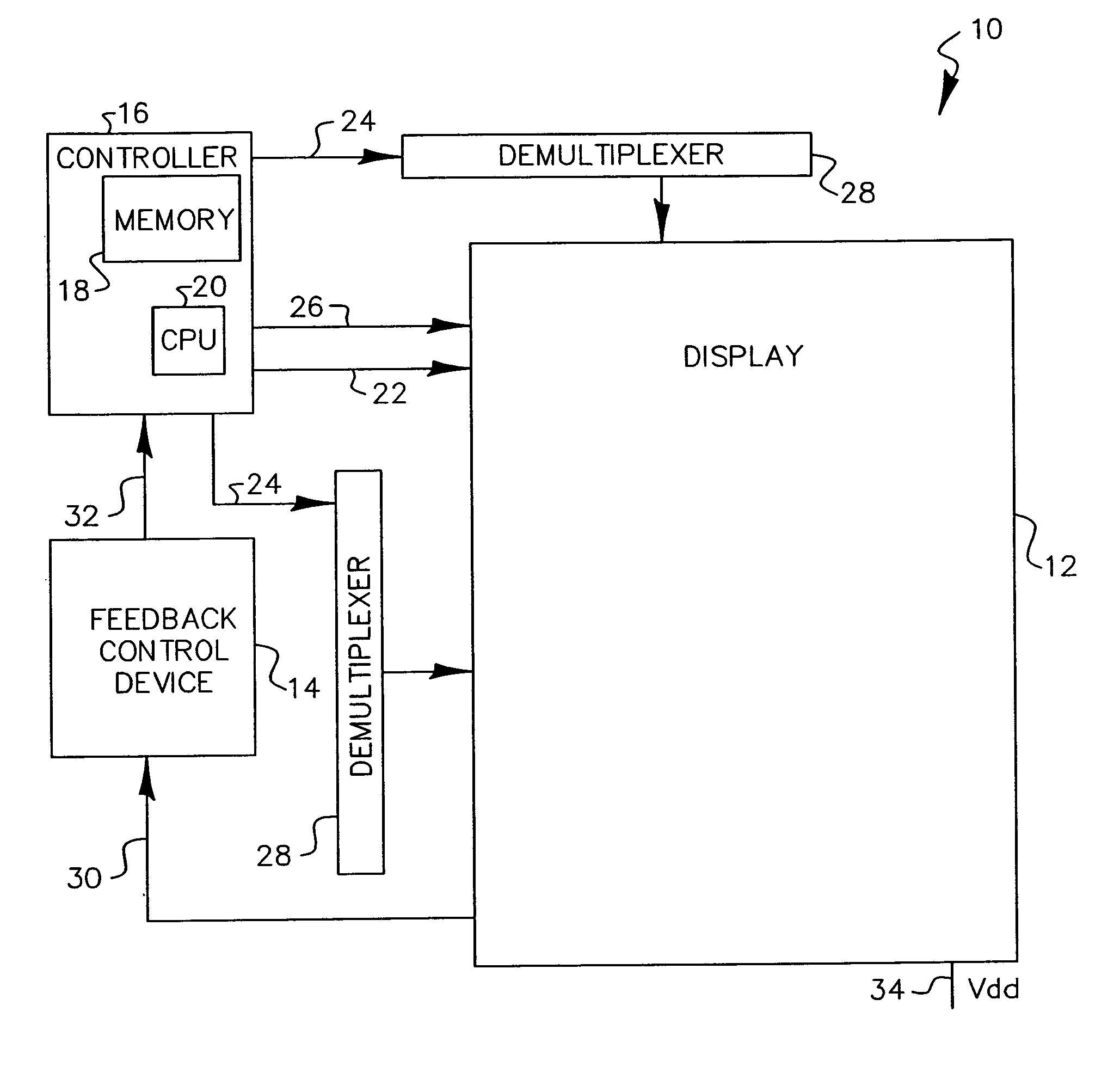
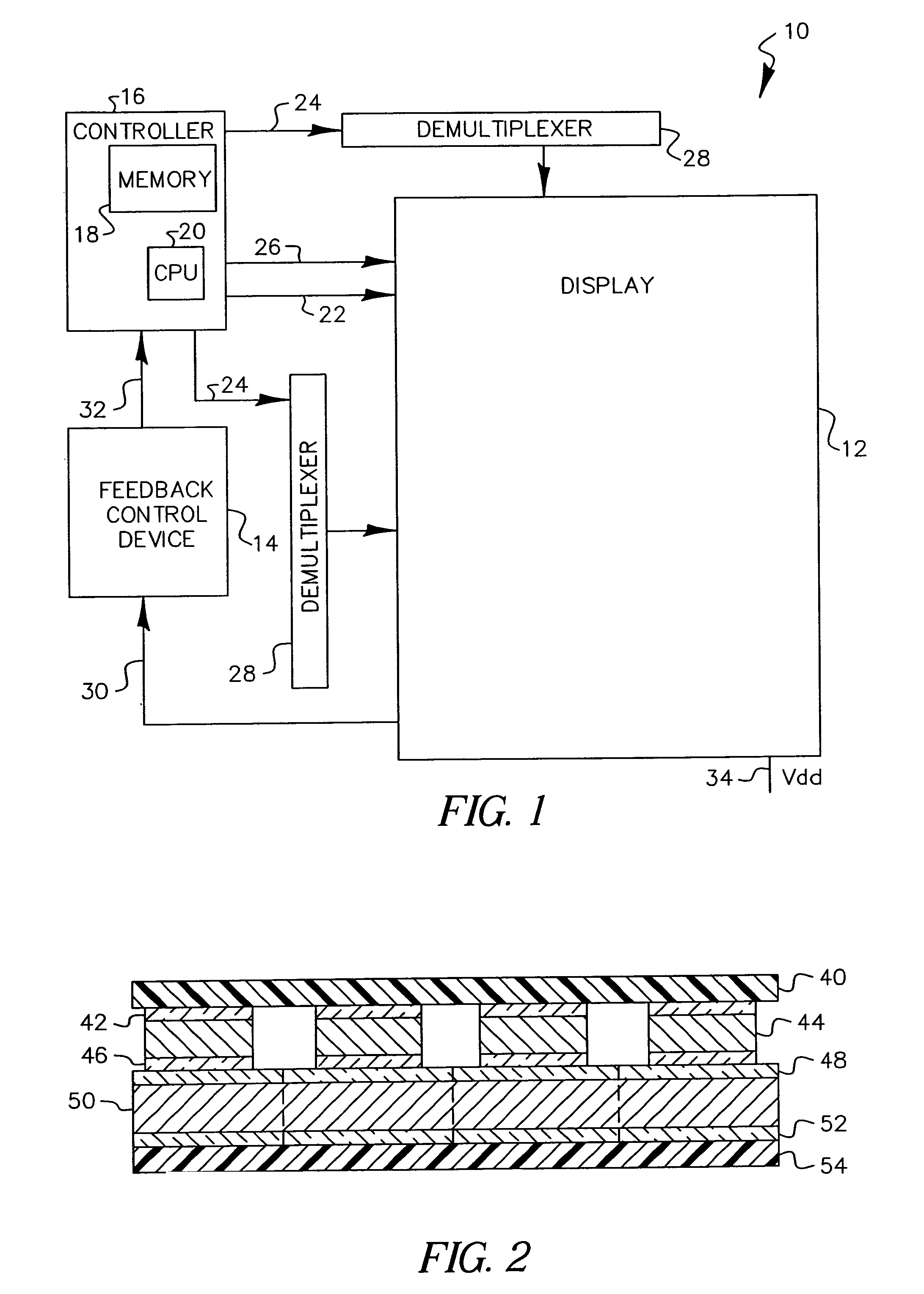
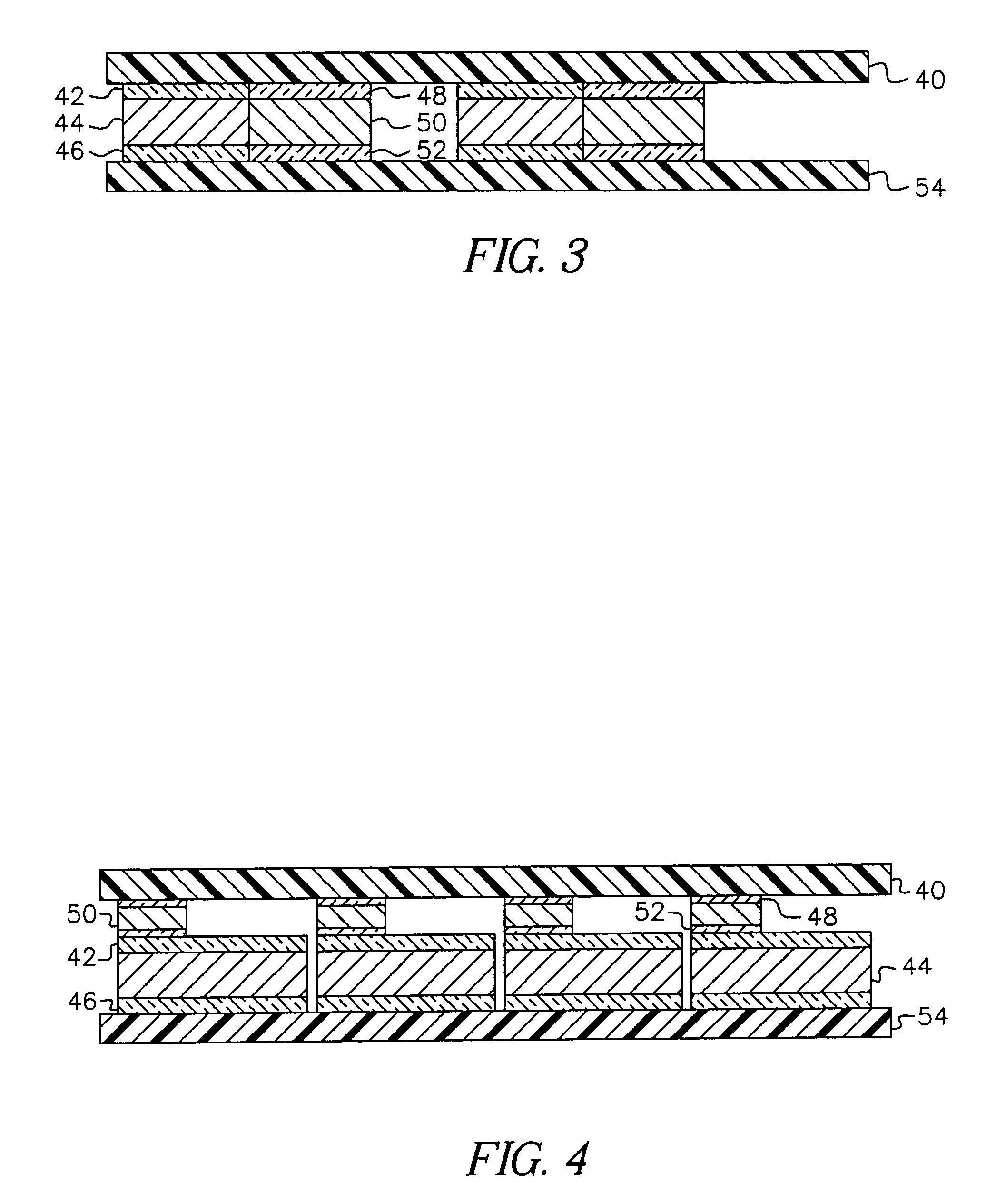
[0023]The present invention is a solid-state display device with addressable light emitting pixels that overcomes the problems in the prior art through the use of optical detector(s) integrated on the display and directly optically coupled with the light emitters of the display. The optical detector(s) produces current dependent on the light emitted from the light emitters. This current is then used as a feedback mechanism to control the current passed through the light emitting pixels to achieve the desired light output.

[0024]The apparatus operates as follows. A display system 10 in FIG. 1 includes a display 12 with a feedback control device 14 and a controller 16 which drives the display. The controller 16 can be an analog device or, as shown, a computer with a memory 18 for instructions and data and a central processing unit 20. The controller writes data to particular display elements using, data, address, and control signals, represented by signals 22, 24, and 26, respectively...


PUM


Abstract

An image display, includes a substrate; a light emitter formed on the substrate; and a photo-sensor formed on the substrate and optically coupled directly to the light emitter.

Description

CROSS REFERENCE TO RELATED APPLICATIONS[0001]This is a Continuation of application Ser. No. 09 / 675,346, filed Sep. 29, 2000 by Ronald S. Cok et al., entitled A FLAT-PANEL DISPLAY WITH LUMINANCE FEEDBACK.FIELD OF THE INVENTION[0002]The present invention relates to solid-state flat-panel display devices and more particularly to such display devices having means to optimize the luminance of each pixel in the display through the use of optical feedback information from each pixel.BACKGROUND OF THE INVENTION[0003]Solid-state organic light emitting diode (OLED) image display devices are of great interest as a superior flat-panel digital display device. These display devices utilize current passing through thin films of organic material to generate light. The color of light emitted and the efficiency of the energy conversion from current to light are determined by the composition of the organic thin-film material. Moreover, the display devices can be made with exclusively transparent mater...

Claims


Application Information

Patent Timeline
Patent Type & Authority Patents(United States)
IPC IPC(8): G09G3/30H01L51/50G09G3/20G09G3/32H01L27/32H05B44/00
CPCG09G3/3216G09G3/3258H01L27/3269G09G2320/0285G09G2320/029G09G2320/043H01L27/3281G09G2320/0626G09G2360/144G09G2360/145G09G2360/148G09G2320/045H10K59/13H10K59/17G09G3/30
Inventor COK, RONALD S.TANG, CHING W.
Owner GLOBAL OLED TECH
Why Eureka
Try Eureka