Refractometer

Inactive Publication Date: 2006-06-20
TESTO AG
View PDF6 Cites 20 Cited by
  • Summary
  • Abstract
  • Description
  • Claims
  • Application Information

AI Technical Summary

Problems solved by technology

Sampling in the case of the first above-named variant is relatively complicated and time-consuming, and the instrument must be thoroughly cleaned before each sampling.
In the instrument of the second variant, the problem often arises that the refractometer has a temperature which is different from that of the

Method used


Image

  • Refractometer
  • Refractometer
  • Refractometer

Examples


Embodiment Construction

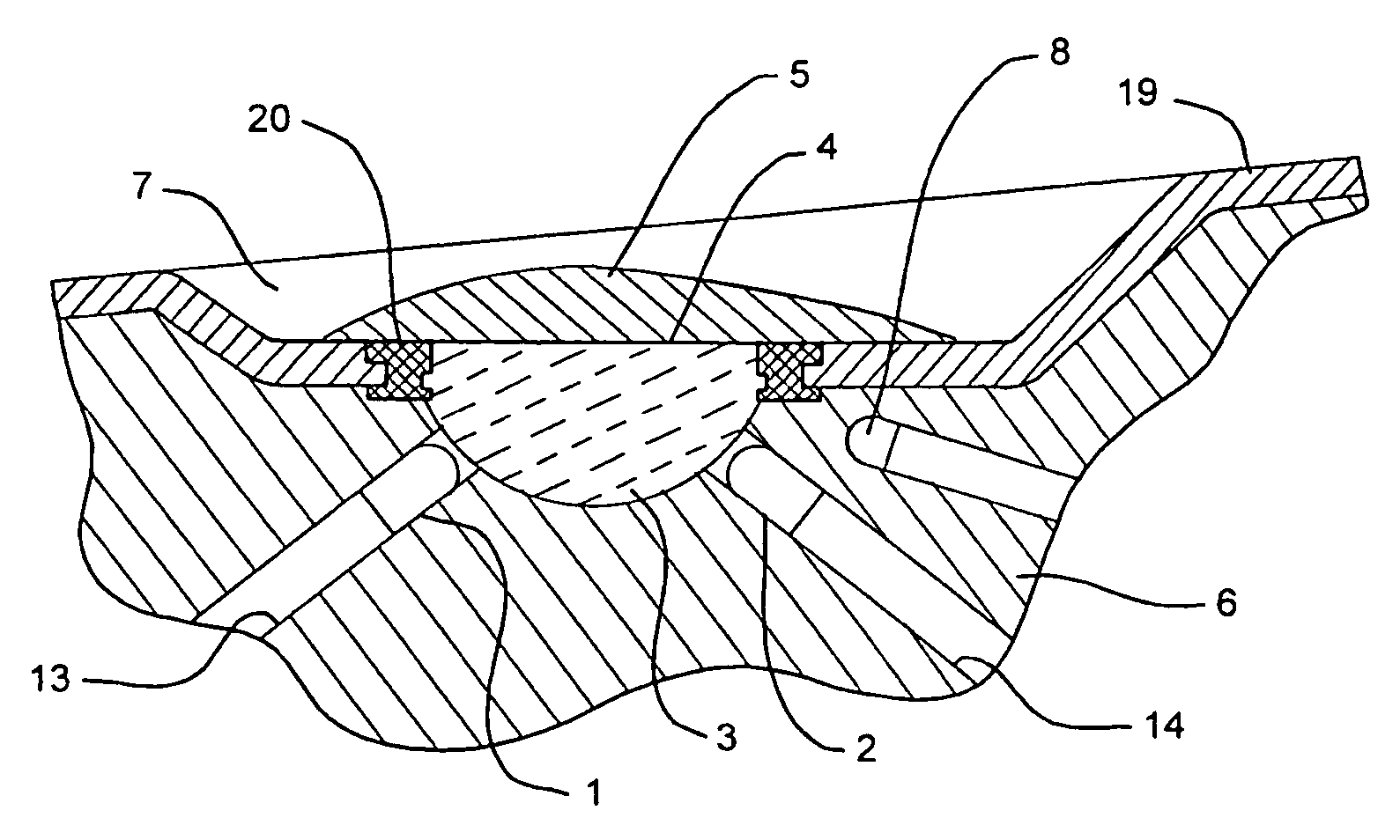
[0032]Initially the operating principle of the refractometer according to the present invention will be elucidated on the basis of FIG. 1. The sensor system having radiation source 1 in the form of an infrared LED, beam detector 2 in the form of a light-sensitive semiconductor diode and the measuring path between them is schematically illustrated. A measuring beam is emitted from radiation source 1 to glass lens body 3 and enters, through its spherical or approximately spherical surface, perpendicularly into the glass body, through which it propagates to measuring surface 4, which is formed by a flat delimiting surface of lens body 3. The measuring beam is reflected or partly refracted there into the liquid as a function of the ratio between the refractive numbers (refractive indices) of the material of the lens body and the material of liquid 5 which wets the lens body.

[0033]At least one portion of the beam may be reflected on measuring surface 4 to beam detector 2 and detected by ...


PUM


Abstract

The invention relates to a portable refractometer comprising a depression (7) for samples, located on an insertion tip (11) in such a way that once the insertion tip (11) has penetrated a liquid or a fruit, a sufficient quantity of the sample liquid remains in the depression (7) for samples, thus wetting a measuring surface (4) that is delimited in said depression by a transparent body. The refractive index of the wetting liquid can be determined by measuring the intensity of an optical beam that is reflected by the measuring surface (4).

Description

BACKGROUND OF THE INVENTION[0001]1. Technical Field[0002]The present invention relates to a refractometer for determining the refractive index of a liquid and, optionally, variables derived therefrom such as, for example, a sugar concentration, having a sensor system which has a radiation source for generating a measuring beam, a beam detector for detecting the measuring beam, and a measuring path to be traveled by the measuring beam, on which path a measuring surface to be wetted by the liquid and which interacts with the measuring beam is situated.[0003]2. Description of the Related Art[0004]Such refractometers are used as digital or analog measuring instruments, for example, for determining the concentration of certain substances dissolved in a liquid and influencing the refractive index. For example, in wine-making, the determination of the sugar content in the grape juice is an important area of application of such measurements.[0005]Two types of measuring instruments are basic...

Claims


Application Information

Patent Timeline
IPC IPC(8): G01N21/41G01N21/43G01N33/14
CPCG01N33/143G01N21/431
Inventor LANGENBACHER, MARKUSDERR, ANDREASEDER, FRANK
Owner TESTO AG
Why Eureka
Try Eureka