Method for producing organic insulating coating and ink-jet printhead produced according to the method

a technology of organic insulating coating and inkjet printing, which is applied in the direction of coatings, pretreated surfaces, printing, etc., can solve the problems of high ink durability, difficult miniaturization of printheads, and difficult increase of nozzle density of printheads

Active Publication Date: 2006-06-27
SHARP KK
View PDF9 Cites 11 Cited by
  • Summary
  • Abstract
  • Description
  • Claims
  • Application Information

AI Technical Summary

Benefits of technology

[0023]In this configuration, an organic insulating coating includes at least the two layers of the first organic coating which is formed on the substrate and the second organic coating which is formed on the first coating, with at least either one of the first organic coating and the second organic coating treated with heat. Consequently occurrence of pinholes is prevented in either one of the two layers of organic coatings, such that insulating properties of the organic insulating coating is improved.
[0032]In this configuration, the protective coating for the electrodes in the ink chambers of an ink-jet printhead includes two or more layers of the organic coatings with at least one of the layers treated with heat. The configuration ensures that the electrodes formed in the ink chambers to be filled with ink are insulated from the ink by the organic coating in which occurrence of pinholes is prevented.

Problems solved by technology

In the Kyser-type printers, however, printheads are difficult to miniaturize and nozzle density thereof is difficult to increase.
In the thermal ink-jet printers, although a high nozzle density is obtainable, since the energy of bubbles produced in ink by heating the ink with a heater is used to eject ink droplets, high ink durability is required, long life of the heater is hard to obtain, and power consumption is high.
However, when the poly-p-xylylene coating is in use as the insulating coating for electrodes in ink chambers of an ink-jet printhead, there occurs a problem as described below.
However, the parylene coating grown with the concavities and convexities of the base reflected has microscopic flaws (pinholes).
Since aqueous ink is an electrolyte solution with a very high electrical conductance in comparison with oil-based ink, if there is a pinhole through an insulating coating separating an electrode and the aqueous ink in an ink chamber, the electrode is electrically conducted with another electrode in an adjacent ink chamber through the ink infiltrating through the pinhole, so that electrolyte corrosion of the electrodes occurs.
This causes ink-jet printhead reliability problems such as fluctuations in ink-ejecting properties during operation of an ink-jet printhead and inferiority in ink ejection in the ink-jet printhead caused by breaking of electrode wires.
These problems also occur in an organic insulating coating formed over another kind of substrate such as a semiconductor.
According to the method, however, equipment is required for the electrodeposition of polyimide resin, thereby increasing production costs.
Also, it is necessary to sinter the polyimide resin for a long time, so that production throughput is decreased.
According to the method, however, vacuum equipment is required for the plasma treatment, thereby increasing production costs.

Method used


Image

  • Method for producing organic insulating coating and ink-jet printhead produced according to the method
  • Method for producing organic insulating coating and ink-jet printhead produced according to the method
  • Method for producing organic insulating coating and ink-jet printhead produced according to the method

Examples


Embodiment Construction

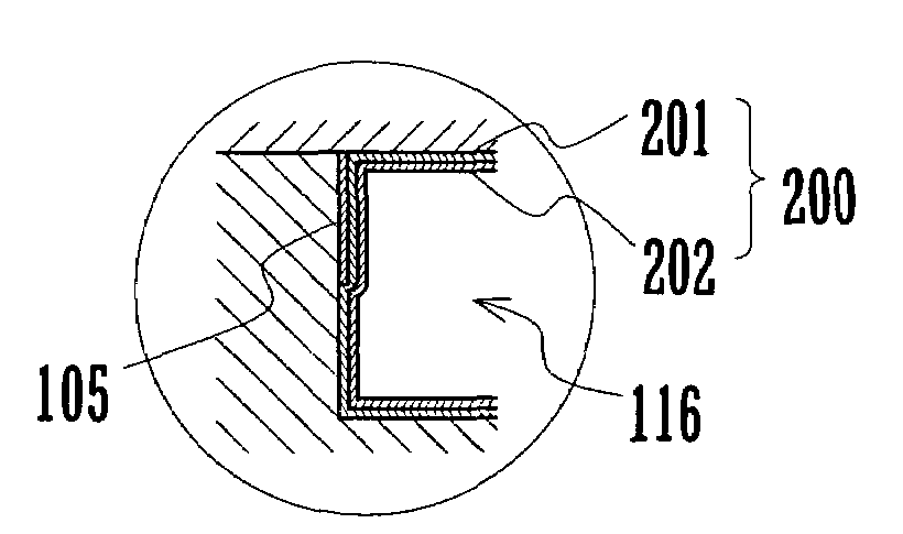
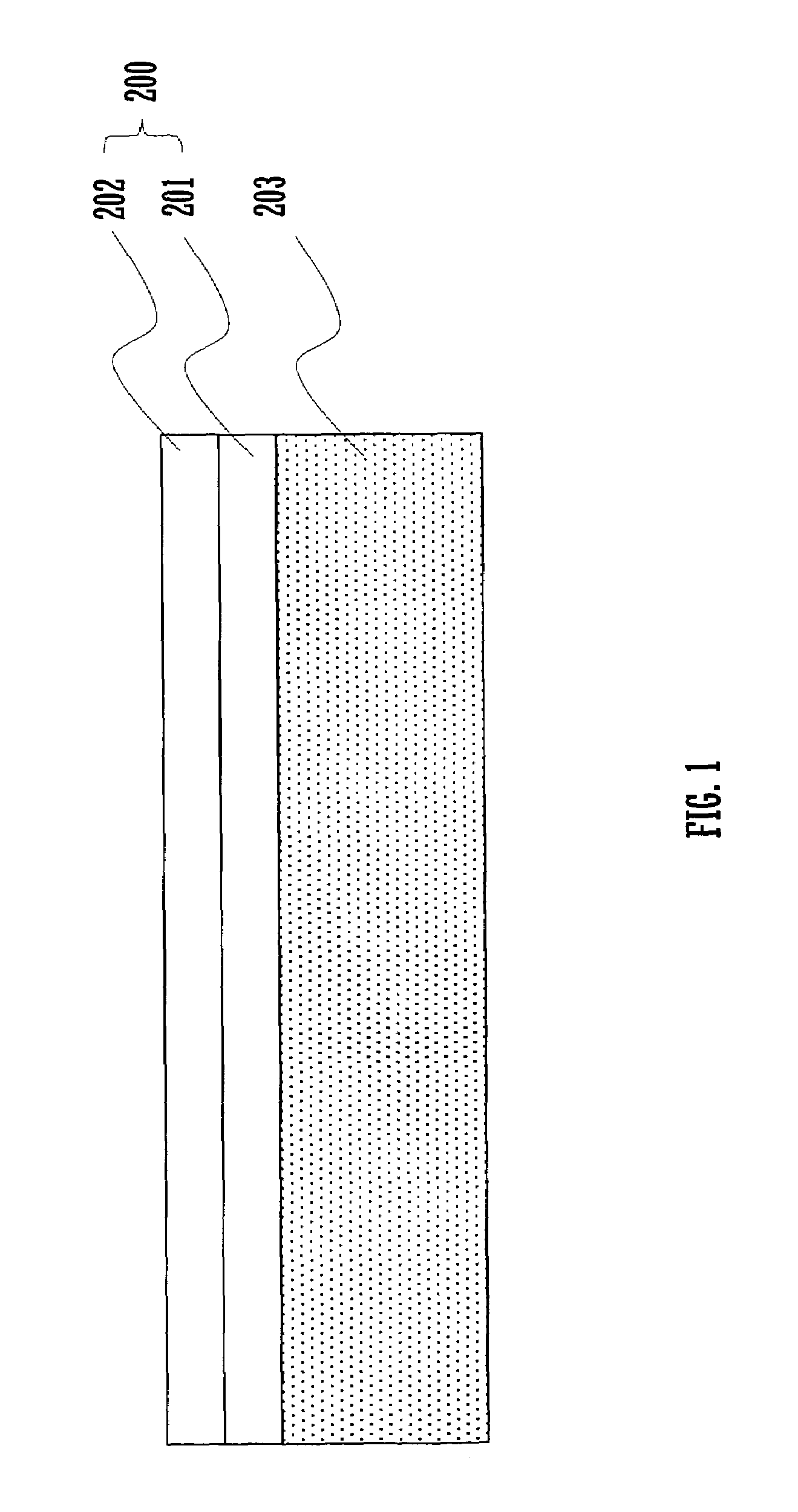
[0044]FIG. 1 is a diagram showing a configuration example of an organic insulating coating formed on a substrate according to a method for producing an organic insulating coating of the present invention. An organic insulating coating 200 formed on a surface of a substrate 203 is composed of a first organic coating 201 and a second organic coating 202, each of which is a parylene-based organic coating (hereinafter referred to as a parylene coating) of thickness 2 μm.

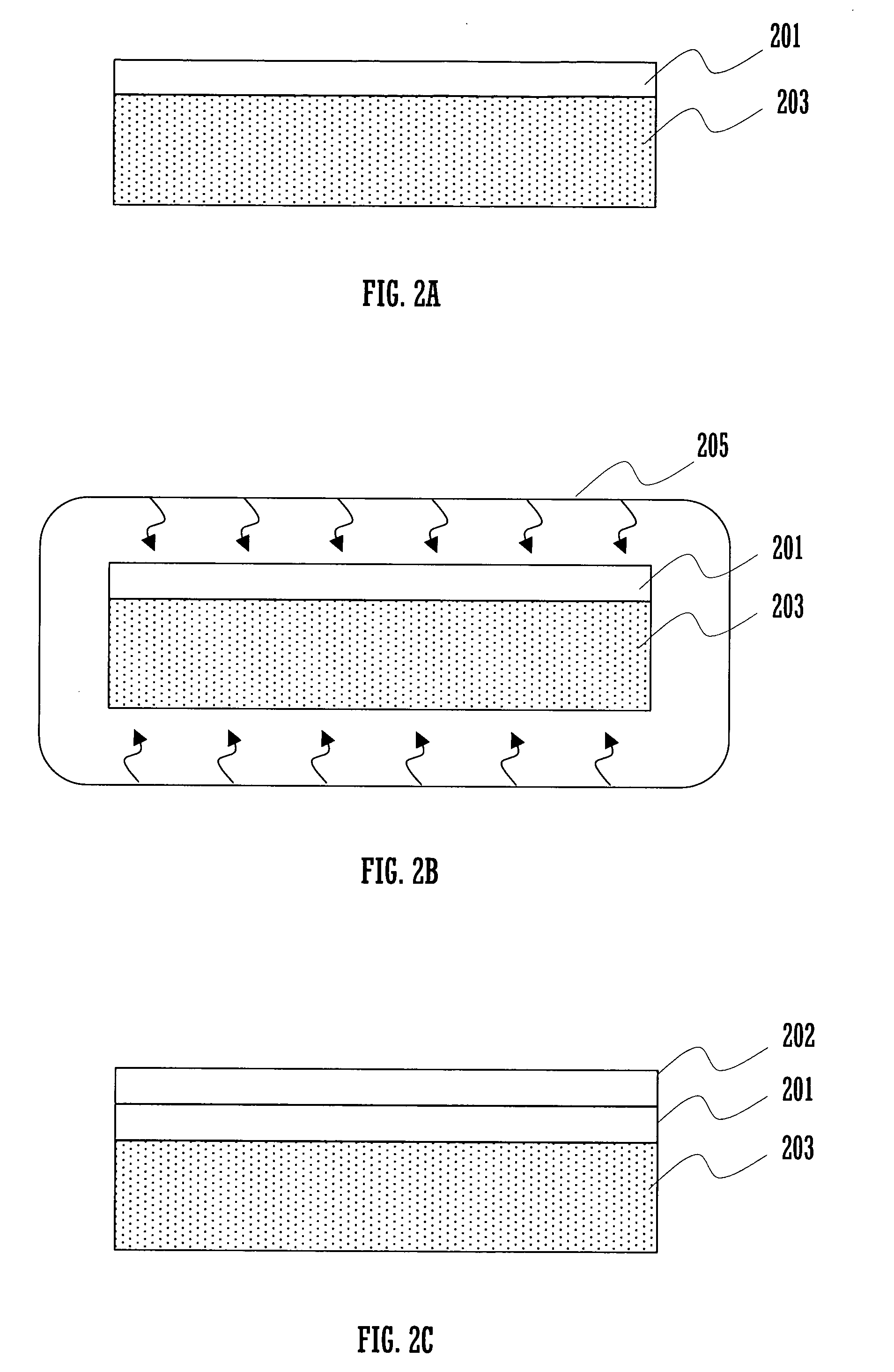
[0045]FIGS. 2A to 2C are diagrams illustrating a method for producing the organic insulating coating. When the organic insulating coating 200 is formed on the substrate 203, the parylene coating 201 is first formed to have thickness 2 μm on the substrate 203, as shown in FIG. 2A.

[0046]Then, as shown in FIG. 2B, the substrate 203 with the first parylene coating formed thereon is placed in a heating device 205 such as an oven to be heated at 100° C. for two hours in the atmosphere. Although an oven is used for heating the ...


PUM

PropertyMeasurementUnit
timeaaaaaaaaaa
temperatureaaaaaaaaaa

Abstract

An organic insulating coating formed on a substrate is composed of two layers of a first parylene coating and a second parylene coating. Heat treatment is performed to at least the first parylene coating after being formed, at a temperature below 125° C. for two hours. Then the second parylene coating is formed on the first parylene coating. Occurrence of pinholes is thus prevented at least in one of the two layers of the organic coatings, with the result that insulating properties of the coatings are improved.

Description

BACKGROUND OF THE INVENTION[0001]1. Technical Field of the Invention[0002]The present invention relates to a method for producing an organic insulating coating such as a protective coating for electrodes in ink chambers of an ink-jet printhead, and further to an ink-jet printhead produced according to the method.[0003]2. Description of Related Art[0004]In place of impact printers, there has been a rapid diffusion of non-impact printers suitable for color and multiple-tone printing such as ink-jet printers. In particular drop-on-demand printers, which eject ink droplets only when needed to print on media, are popular because of their improved printing efficiency and low production and running costs. Most of the drop-on-demand printers today are using a Kyser method utilizing piezoelectric elements or a thermal ink-jet method.[0005]In the Kyser-type printers, however, printheads are difficult to miniaturize and nozzle density thereof is difficult to increase. In the thermal ink-jet pr...

Claims


Application Information

Patent Timeline
Patent Type & Authority Patents(United States)
IPC IPC(8): B41J2/045B41J2/05B05D3/02B05D5/12B41J2/055B41J2/16
CPCB41J2/1606B41J2/1609B41J2/164B41J2/1632B41J2/1623
Inventor DEGUCHI, HARUHIKOKAKIWAKI, SHIGEAKIMATOBA, HIROTSUGUNAKAMURA, HIROKAZUMATSUSHITA, MASAKITANAKA, TOMOMI
Owner SHARP KK
Why Eureka
Try Eureka