Method for the production of electrocatalyst powders

a technology of electrocatalyst and powder, which is applied in the field of powder production of electrocatalyst, can solve the problems of low power of zinc-air batteries, limited total power, and poor rechargeability/cycle li

Inactive Publication Date: 2006-06-27
CABOT CORP
View PDF68 Cites 48 Cited by
  • Summary
  • Abstract
  • Description
  • Claims
  • Application Information

AI Technical Summary

Benefits of technology

[0126]It is an advantage of the present invention that the composition of the electrocatalyst particles can be homogeneous. A degree of homogeneity in materials is often not obtainable by traditional forming methods such as liquid precipitation. However, it is also possible to intentionally provide compositional gradients within the electrocatalyst particles. For example, the active species concentration in a composite particle can be higher or lower at the surface of the support phase than near the center and gradients corresponding to compositional changes of 10 to 100 weight percent can be obtained. When the particles are deposited by direct-write deposition, the particles retain their structural morphology and therefore the functionality of the compositional gradient can be exploited.
[0127]The preferred form of carbon for crystalline supported active species are those which are amorphous. The preferred carbons for supported metals like Pt are carbons that are crystalline since Pt dispersion is favored by reduced carbon surfaces with substantially no surface hydroxyls. For supported MnOx, it is also preferred to have a crystalline carbon support. Preferably, the crystallinity of the primary particles constituting the support phase is controlled through the selection of materials chosen for a specific application. Graphitic carbon is preferred for long term operational stability of fuel cells and batteries. Amorphous carbon is preferred when a smaller crystallite size is desired for the supported active species.
[0128]The overall density of the secondary support phase in the composite particles is related to the porosity of the support phase. It is preferred that the accessible (e.g., open) porosity in the composite electrocatalyst particles is from about 5 to 98 percent and more preferably is at least about 40 percent. The pore size distribution in the secondary support phase can also be controlled and the average pore size is preferably from about 10 to about 100 nanometers. High porosity is advantageous for rapid transport of species into and out of the secondary structures. Lower particle densities also allow easier suspension of the particles for printing techniques such as ink-jet deposition where suspension of particles for long periods is required. As an example, an aerogel carbon or metal oxide can have a density much lower than 1 g / cm3.
[0129]Agglomeration of the electrocatalyst particles can affect the properties of the powder batch such as the ability to disperse the powder into liquids used to deposit the particles. It is therefore preferred that minimal agglomeration of the particles exist in the powder batch.
[0130]It is also an advantage of the present invention that the electrocatalyst particles are substantially spherical in shape. That is, the particles are preferably not jagged or irregular in shape. Spherical particles can advantageously be deposited using a variety of techniques, including direct write deposition, and can form layers that are thin and have a high packing density.
[0131]In addition, the composite electrocatalyst powders according to the present invention preferably has a surface area of at least about 25 m2 / g, more preferably at least about 90 m2 / g and even more preferably at least about 600 m2 / g. Surface area is typically measured using the BET nitrogen adsorption method which is indicative of the surface area of the powder, including the surface area of accessible pores on the surface of the particles. High surface area generally leads to increased catalytic activity.

Problems solved by technology

The two major problems associated with secondary zinc-air batteries, however, are limited total power and poor rechargeability / cycle lifetime.
The main reason for the low power of zinc-air batteries is believed to be related to the inefficiency of the catalytic reaction to reduce oxygen in the air electrodes.
Poor accessibility of the catalyst and the local microstructural environment around the catalyst and adjoining carbon reduces the efficiency of the oxygen reduction.
Rechargeability is also a problem with zinc-air batteries.
Specifically, it is believed that corrosion of the carbon used for the electrocatalyst in these systems leads to a loss in capacity and hence, a decreased discharge time.
A significant obstacle to the wide-scale commercialization of such devices is the need for highly efficient electrocatalyst materials for this conversion process.
The critical issues that must be addressed for the successful commercialization of fuel cells are cell cost, cell performance and operating lifetime.
Platinum metal is very expensive and a significant cost reduction in the electrocatalyst is necessary for these cells to become economically viable.
However, reducing the amount of precious metal is not a suitable solution because there is also a strong demand for improved cell performance which relies on the presence of the platinum electrocatalyst.
The major technical challenge is improving the performance of the cathode with air as the oxidant.
The foregoing method generally results in poor control over the composition and microstructure of the composite powders.
The inability to control the fundamental electrocatalyst powder characteristics is a major obstacle for the future development of energy storage and production devices.
The foregoing methods generally result in poor control over the composition and microstructure of the electrocatalytic materials, as well as poor control over the dispersibility and surface area of the active species on the carbon surface.
Further, alloy compositions such as platinum / ruthenium used for oxygen reduction in a fuel cell are not made in a consistently reproducible fashion.
The inability to control the fundamental powder characteristics is a major obstacle to the development of more efficient electrocatalyst materials.

Method used


Image

  • Method for the production of electrocatalyst powders
  • Method for the production of electrocatalyst powders
  • Method for the production of electrocatalyst powders

Examples


examples

1. MnOx / C Composite Particles

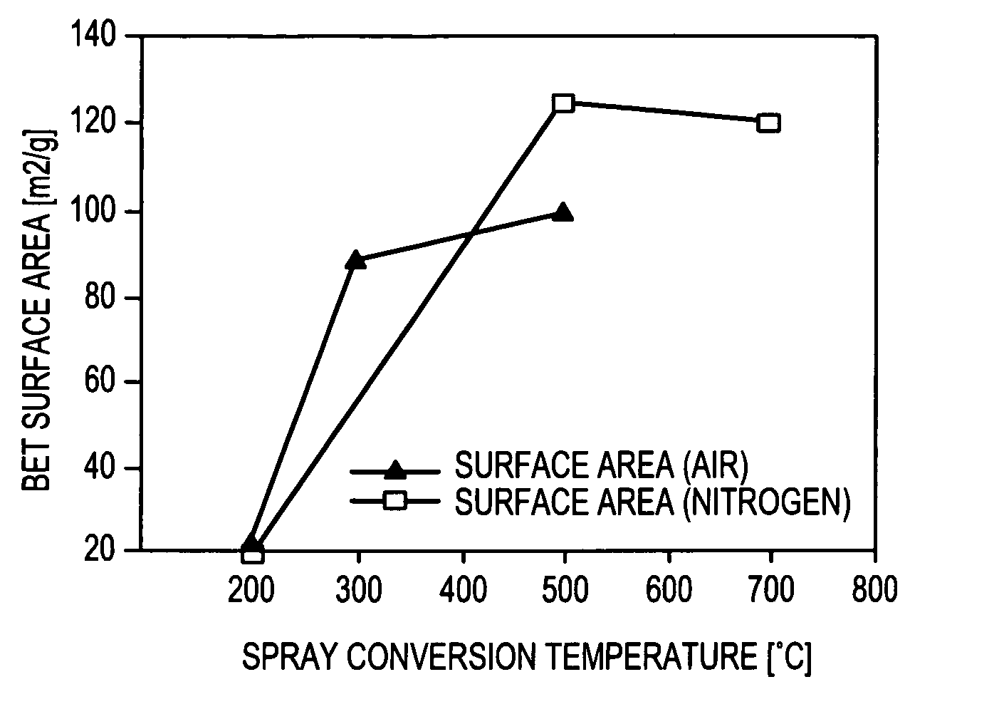
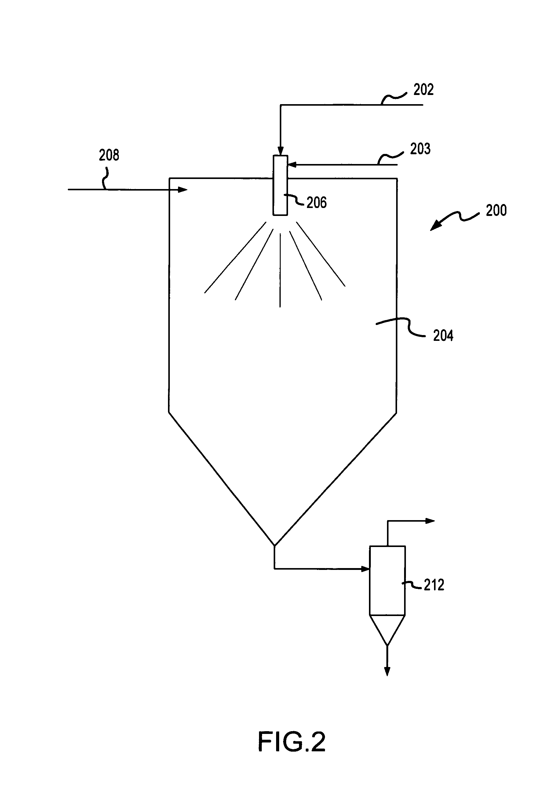
[0324]Two groups of MnOx / C composite electrocatalyst examples were prepared according to the present invention. The first group, described in Table I, was prepared by ultrasonic aerosol generation and heating the aerosol in a hot-wall reactor (tubular furnace). The second group, described in Table II, was prepared using a spray nozzle to generate an aerosol which was heated in a spray dryer. Air was used for the carrier gas for all examples.

[0325]

TABLE IExperimental conditions for ultrasonically generated electrocatalystsPrecursorAdditionalReactorConcen-ExampleMn SurfactantTempMntrationNumberprecursor(wt. %)(° C.)(wt. %)(wt. %)19AKMnO4None40010519BMn nitrateNone35010520AKMnO4None35010520BKMnO4None35010523AKMnO40.01735010524AKMnO40.03435010527AMn nitrate0.04935010528BKMnO40.04930010528DKMnO40.04925010528EKMnO40.04920010529BMn nitrate / 0.012350105KMnO4

[0326]

TABLE IIExperimental conditions for spray nozzle generated electrocatalystsPrecursorAdditionalReactor...


PUM

PropertyMeasurementUnit
temperatureaaaaaaaaaa
reaction temperatureaaaaaaaaaa
sizeaaaaaaaaaa

Abstract

Electrocatalyst powders and methods for producing electrocatalyst powders, such as carbon composite electrocatalyst powders. The powders have a well-controlled microstructure and morphology. The method includes forming the particles from an aerosol of precursors by heating the aerosol to a relatively low temperature, such as not greater than about 400° C.

Description

[0001]This is a continuation application of U.S. patent application Ser. No. 09 / 532,917 filed on Mar. 22, 2000, now U.S. Pat. No. 6,660,680 which is a continuation-in-part application of U.S. patent application Ser. No. 09 / 141,397 filed Aug. 27, 1998 now U.S. Pat. No. 6,103,393, which in turn is a continuation-in-part application of U.S. patent application Ser. Nos. 09 / 028,029, now abandoned, 09 / 028,277 now U.S. Pat. No. 6,277,169, and 09 / 030,057 now U.S. Pat. No. 6,338,809, each filed on Feb. 24, 1998.STATEMENT REGARDING FEDERALLY FUNDED RESEARCH[0002]This invention was made with United States Government support under Cooperative Agreement No. 70NANB8H4045 awarded by the National Institute for Standards and Technology (NIST).BACKGROUND OF THE INVENTION[0003]1. Field of the Invention[0004]The present invention relates to particulate materials such as electrocatalyst powders for the fabrication of energy devices and to methods for producing such powders, as well as products and devic...

Claims


Application Information

Patent Timeline
Patent Type & Authority Patents(United States)
IPC IPC(8): B22F9/28B01J2/02B01J13/02B01J19/00B01J19/10B01J19/24B01J21/18B01J23/00B01J23/34B01J23/40B01J31/06B01J35/02B01J35/08B01J35/10B01J37/00B01J37/34B22F1/054B22F9/02B22F9/24C01B13/18C01B17/20C01G23/00C22C29/00C22C32/00H01L23/498H01M4/86H01M4/90H01M4/92H01M8/10H01M12/08H05K1/09
CPCB01J2/02B01J19/10B01J19/2405B01J21/18B01J23/34B01J23/40B01J35/023B01J35/10B01J37/0054B22F1/0018B22F9/026B22F9/24B82Y30/00C01B13/18C01B17/20C01G23/003C22C29/00C22C32/0084H01L23/49883H01M4/8605H01M4/90H01M4/9083H01M4/926B01J13/02Y10T29/53204B01J23/00B01J31/06B01J35/08B01J37/343B01J2219/00112B01J2219/00155B01J2219/00159B01J2219/00162B01J2219/00166B01J2219/00171B01J2219/00186B22F2998/00C01P2004/32C01P2004/61C01P2006/22H01M4/9016H01M8/1004H01M12/08H05K1/095Y10T29/49108Y10T29/532Y10T29/5313Y10T29/53135Y10T29/49115H01L2924/0002Y02E60/50B22F1/0048B22F1/0014B22F1/025H01L2924/00B01J35/002B01J35/0033B01J35/006B01J35/1014Y02P70/50B22F1/054B22F1/065B22F1/18B22F1/052Y02E60/10
Inventor HAMPDEN-SMITH, MARK J.KODAS, TOIVO T.ATANASSOV, PLAMENATANASSOVA, PAOLINAKUNZE, KLAUSNAPOLITANO, PAULDERICOTTE, DAVID
Owner CABOT CORP
Why Eureka
Try Eureka